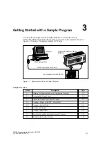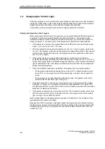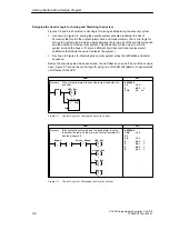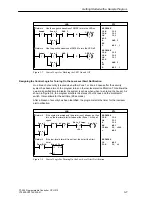
3-3
S7-200 Programmable Controller, CPU 210
C79000-G7076-C235-01
Kitchen
Bath
Bedroom 3
Bedroom 2
Bedroom 1
Living Room
Front
Entrance
Rear
Entrance
D
C
B
A
E
F
I
H
J
K
L
M
Zone 1
Zone 2
Figure 3-2
Sample Application for a Home Security System
Modem Dialer
Relay
Q0.0
Q0.2
I0.0
I0.1
I0.2
I0.3
1M
A
B
C
D
E
F
Zone 1
“Panic” Alarm
Arm/Disarm System
System LED
High-level Alarm
Low-level Alert
Inputs
Outputs
H
I
J
K
L
M
Zone 2
Q0.1
2L
Q0.3
1L
Figure 3-3
Wiring Diagram for the Sample Home Security Application
Getting Started with a Sample Program
Summary of Contents for Simatic S7-200 CPU 210
Page 10: ...x S7 200 Programmable Controller CPU 210 C79000 G7076 C235 01 Contents ...
Page 116: ...A 16 S7 200 Programmable Controller CPU 210 C79000 G7076 C235 01 CPU 210 Data Sheets ...
Page 126: ...F 2 S7 200 Programmable Controller CPU 210 C79000 G7076 C235 01 CPU 210 Order Numbers ...
Page 138: ...Index 12 S7 200 Programmable Controller CPU 210 C79000 G7076 C235 01 Index ...


