background image

Getting Started

3-9

Windows Automation Center WinAC Slot 412/WinAC Slot 416 Version 3.1
A5E00065531-03

Figure 3-7

Bus Connection

Summary of Contents for SIMATIC WinAC Slot 412

Page 1: ...nAC Slot 41x 2 Getting Started 3 Using the Tool Manager 4 Appendices Index 06 2000 A5E00065531 03 Windows Automation Center WinAC Slot 412 WinAC Slot 416 Version 3 1 Overview This manual is part of the documentation package with order no 6ES7 673 6CC01 8BA0 SIMATIC ...

Page 2: ...ed cor rectly and operated and maintained as recommended Trademarks WinAC SIMATIC SIMATIC HMI and SIMATIC NET are registered trademarks of SIEMENS AG Some of other designations used in these documents are also registered trademarks the owner s rights may be violated if they are used by third parties for their own purposes Safety Guidelines This manual contains notices which you should observe to e...

Page 3: ...utomation Center WinAC allow you the combined solution consisting of data processing control visualization and communications on your PC PC based control The following versions of the WinAC product are available WinAC Slot 412 WinAC Slot 416 This manual will familiarize you with the individual components of the WinAC Slot 412 and WinAC Slot 416 product versions by way of an overview ...

Page 4: ...ard Description of control panel router time synchronization Technical specifications Compatibility with CPU 416 2 DP ISA CPU 416 2 DP ISA Lite Manual SIMATIC Computing Function and running of the SIMATIC Computing software Description of the controls S7 400 instruction list Instruction set for all CPUs Brief description of instructions and execution times List of OBs system events SSL IDs SFCs SF...

Page 5: ...f courses to help get you started with the SIMATIC S7 automation system Please contact your local training center or the central training center in Nuremberg D 90327 Germany tel 49 911 895 3200 Constantly updated information You can obtain up to the minute information on SIMATIC products On the Internet at http www ad siemens de By dialing the fax polling number 49 8765 93 00 55 00 In addition the...

Page 6: ...Important Information vi Windows Automation Center WinAC Slot 412 WinAC Slot 416 Version 3 1 A5E00065531 03 ...

Page 7: ...e SIMATIC Computing across a DCOM Network 1 14 1 11 Using OPC to Connect Third Party Applications to SIMATIC Computing 1 15 1 12 The WinAC Tool Manager Provides Shortcuts to Your Programs 1 16 2 Installing WinAC Slot 41x 2 1 Overview of the Installation 2 1 2 2 Installing and Uninstalling the WinAC Slot 41x Software 2 3 3 Getting Started 3 1 The Task Communications Via the Router 3 2 3 1 1 Creatin...

Page 8: ...ting 1 15 1 12 WinAC Tool Manager and Shortcut Icon 1 16 2 1 Installing the Components of WinAC Slot 41x 2 2 3 1 Communication via the Router 3 2 3 2 Creating a Project 3 3 3 3 Selecting a Mounting Rack 3 4 3 4 Assigning a CP 3 5 3 5 Configuring the Hardware of the S7 400 Station 3 6 3 6 MPI Connection 3 7 3 7 Bus Connection 3 9 3 8 Creating a Connection 3 10 3 9 Connection Properties 3 11 3 10 Se...

Page 9: ...dustrial Ethernet or PROFIBUS or a network card the time synchronization for synchronization of the CPU 41x 2 PCI via a SIMATIC NET CP Industrial Ethernet or PROFIBUS the SIMATIC Computing software The SIMATIC Computing software provides ActiveX controls which you can use specifically to visualize your process In SIMATIC Computing you can use third party ActiveX controls in addition to S7 Controls...

Page 10: ...cations to SIMATIC Computing 1 15 1 12 Tool Manager Provides Shortcuts to Your Programs 1 16 1 1 What Are WinAC Slot 412 and WinAC Slot 416 PC based control with WinAC Slot 412 WinAC Slot 416 In the top range of the PLC applications the number of PC tasks such as data processing and visualization is increasing The use of PC based control use of a PC with an integrated PLC is then frequently the so...

Page 11: ...12 2 PCI or CPU 416 2 PCI These CPUs exhibit typical PLC features warm restart restart or precise complete restart as commanded with PS extension board deterministic behavior with real time response times real time clock data retentivity using battery backup with PS extension board external load memory for saving the PLC program independently of the PC hard disk integrated MPI for connecting a pro...

Page 12: ...m the control panel can be protected by a password so that only authorized persons can modify the settings Shows the status of the CPU 41x 2 PCI Resets the memory areas Sets the operating mode of the CPU 41x 2 PCI Figure 1 1 Control Panel Programming Configuration and programming of the CPU 41x 2 PCI is accomplished in a manner similar to that for the SIMATIC S7 with STEP 7 For these tasks you can...

Page 13: ...1 A5E00065531 03 1 2 CPU 41x 2 PCI Is for Controlling Your Process CPU 41x 2 PCI features an effective hardware solution for your automation projects refer to Figure 1 2 The I O is connected via PROFIBUS DP Distributed I O CPU 41x 2 PCI Figure 1 2 Using the CPU 41x 2 PCI in WinAC Slot 41x ...

Page 14: ...y is used to supply voltage to the CPU 41x 2 PCI independently of the PC power supply unit In this way it is possible to operate the CPU 41x 2 PCI even when the PC has been powered down By connecting the backup battery warm restart restart and complete restart are possible for the CPU 41x 2 PCI In addition you can operate the fan in the PC with the PS extension board Figure 1 3 PS Extension Board ...

Page 15: ...U 41x 2 PCI STEP 7 Router Clock synchronization PROFIBUS DP PROFIBUS DP WinCC Windows application transfer via STEP 7 Configure Hardware CPU 41x 2 PCI MPI DP DP Communication CP Industrial Ethernet or PROFIBUS subnet OP OS ET 200M S7 400 PG PC OP OS ET 200S PG PC S7 300 Figure 1 4 Communication Options with the CPU 41x 2 PCI Figure 1 4 shows the communication options open to you with the CPU 41x 2...

Page 16: ...tegrated interface 2 Connection to MPI or PROFIBUS DP through the second integrated interface 3 Connection to PC through the PCI interface 4 Connection to another network such as Industrial Ethernet PROFIBUS via a communication processor CP Note With SIMATIC Manager STEP 7 which is installed on the same PC as the CPU 41x 2 PCI you cannot simultaneously operate the CPU 41x 2 PCI and the CPUs connec...

Page 17: ...on system which are connected to a SIMATIC NET Industrial Ethernet PROFIBUS IE PB to be able to communicate with the CPU 41x 2 PCI a router has to be installed on the programming device or PC and the access points configured Data transfer is possible in both directions Router PC Industrial Ethernet IE PROFIBUS DP PB OP OS S7 Station PG PC IE CP or PB CP CPU 41x 2 PCI Figure 1 5 Communication via t...

Page 18: ...ith the current date and time The time of day transmitter furnishes the time of day at periodic intervals on the Industrial Ethernet or PROFIBUS IE PB Only the ISO protocol is supported by Industrial Ethernet Clock synchronization PC Industrial Ethernet IE PROFIBUS DP PB OP OS S7 station PG PC CPU 41x 2 PCI IE CP or PB CP Time of day transmitter Figure 1 6 Clock synchronization Note The time synch...

Page 19: ...ions across a network A distributed application consists of several processes or different computers that cooperate to jointly solve a task refer to section 1 10 You can use an OPC OLE for Process Control server which other OPC clients use to access the data in the controlled device refer to section 1 11 S7SoftContainer S7Soft1 File Edit View Mode Options Window Help Ready S7Soft1 ÎÎÎÎÎÎÎÎÎÎÎÎÎÎÎÎ...

Page 20: ... creates a tag file that provides a source of symbolic information for the memory locations and control engines The tag file can then be used on a computer on which STEP 7 is not installed Refer to the SIMATIC Computing User Manual for detailed information about using the TagFile Configurator SIMATIC Projects Master_Mixer PC_1 WinAC Mixer Tag File Control Engine Symbol STEP 7 Path PC_1_WinAC WinAC...

Page 21: ...onnect your program to control engines residing on several different computers You use the TagFile Configurator to insert more than one control engine into a tag file Refer to the SIMATIC Computing User Manual for detailed information about using the TagFile Configurator PC 1 CPU 41x 2 PCI SIMATIC Computing PC 2 PC 3 SIMATIC Projects Master_Mixer PC_2 WinAC Mixer Tag File Control Engine Symbol STE...

Page 22: ...quest services from server program objects on other computers in a network In WinAC you can connect distributed applications across a network using DCOM refer to Figure 1 10 A distributed application consists of multiple processes or different computers that cooperate to accomplish a single task jointly Network Client DCOM components I O DCOM components SIMATIC Computing PC 1 CPU 41x 2 PCI PC 2 Se...

Page 23: ...e the OPC server provided with the SIMATIC Computing software to communicate with the control engine and provide access to the process data SIMATIC Computing provides an OPC server that allows any OPC client application to access data in the control engine SIMATIC Computing does not provide any OPC client application The OPC server is called OPCServer WinAC SIMATIC Computing allows you to use OPC ...

Page 24: ...eadsheet you can insert shortcuts to those items on the WinAC Tool Manager The WinAC Tool Manager is especially convenient for users who do not have a mouse on their computer since all of the functions of the WinAC Tool Manager can be accessed by keystrokes from one central location Figure 1 12 shows the WinAC Tool Manager and its shortcut icon You can insert shortcut icons for any of your program...

Page 25: ...commend the following requirements for your computer A personal computer PC with the following Pentium processor running at 166 MHz or faster 32 MB RAM Microsoft Windows NT 4 0 Service Pack 5 or higher A color monitor keyboard and mouse or other pointing device that are supported by Microsoft Windows NT A hard drive with 50 Mbytes of free space At least 25 Mbyte free memory capacity on drive C for...

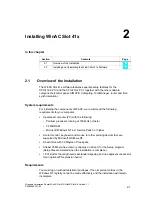
Page 26: ... Slot 41x Section 2 2 explains the steps you have to take to install the software Figure 2 1 shows the dialog box that allows you to choose which components to install Select the components that you want to install Setup automatically highlights the components that it could not find on your PC Figure 2 1 Installing the Components of WinAC Slot 41x ...

Page 27: ...tructions displayed by the installation program one at a time Once the installation has been completed successfully a message to that effect is displayed on the screen If an older version of WinAC has already been installed Before installing your new software you should uninstall any earlier version which may be installed on your computer Overwriting an old version with a new version has the disad...

Page 28: ...efore proceeding to uninstall The corresponding software components must not be in use when the software is uninstalled Uninstalling the components of the WinAC Slot 41x software Perform the following steps to remove the WinAC Slot 41x software from your computer 1 Double click on the Software icon on the Control Panel 2 Select one of the WinAC Slot 41x components you want to have uninstalled from...

Page 29: ...rcises to show you the most important screen based dialog boxes and approaches It will be helpful if you are already in a position to work with a mouse windows pull down menus etc and have a basic knowledge of PLCs There are training courses in which you can add to the knowledge you have acquired with Getting Started and learn how to create complete automation solutions with STEP 7 Requirements fo...

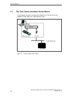
Page 30: ...3 1 A5E00065531 03 3 1 The Task Communications Via the Router In our example we want to connect a PC station to a CPU 416 2 PCI and a SIMATIC S7 400 station via Industrial Ethernet IE Router PC Industrial Ethernet S7 station CPU 416 2 PCI CP 1613 Figure 3 1 Communication via the Router ...

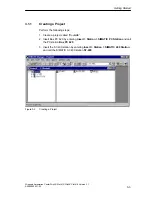
Page 31: ... Project Perform the following steps 1 Create a project called RouterIE 2 Insert Box PC 620 by entering Insert Station SIMATIC PC Station and call the PC station Box PC 620 3 Insert the S7 400 station by entering Insert Station SIMATIC 400 Station and call the SIMATIC S7 400 station S7 400 Figure 3 2 Creating a Project ...

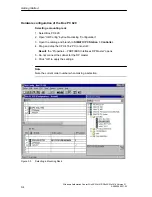
Page 32: ... 2 Open HWConfig by double clicking Configuration 3 Open the catalog and branch to SIMATIC PC Station Controller 4 Drag and drop the CPU 416 2 PCI onto slot 3 Result the Properties PROFIBUS Interfaces DP Master opens 5 Do not connect the subnet for the DP master 6 Click OK to apply the settings Note Note the current order number when making a selection Figure 3 3 Selecting a Mounting Rack ...

Page 33: ...ng a CP 1 Branch to SIMATIC PC Station CP Industrial Ethernet 2 Drag and drop CP 1613 into slot 9 Result the Properties Ethernet Interface CP 1613 dialog box opens 3 Click OK to apply the settings 4 Close with Save and Compile Note Note the current order number when making a selection Figure 3 4 Assigning a CP ...

Page 34: ...f the S7 400 station 1 Select the components listed below and configure them as shown in Figure 3 5 Rack Power supply CPU 416 1 CP 443 1 2 Do not connect the subnet for the CP 443 1 3 Close with Save and Compile Note Note the current order number when making a selection Figure 3 5 Configuring the Hardware of the S7 400 Station ...

Page 35: ...ck the MPI DP node of the Box PC 620 to select it 4 Select MPI 1 from the subnet list 5 Open the properties dialog box change the network name from MPI 1 to MPI Net 6 Set address 2 7 Double click the CPU 416 1 to select it 8 Select MPI Net from the subnet list 9 Open the properties dialog and select MPI Net 10 Set address 10 11 Click OK to apply the dialogue 12 Close with Save and Compile Figure 3...

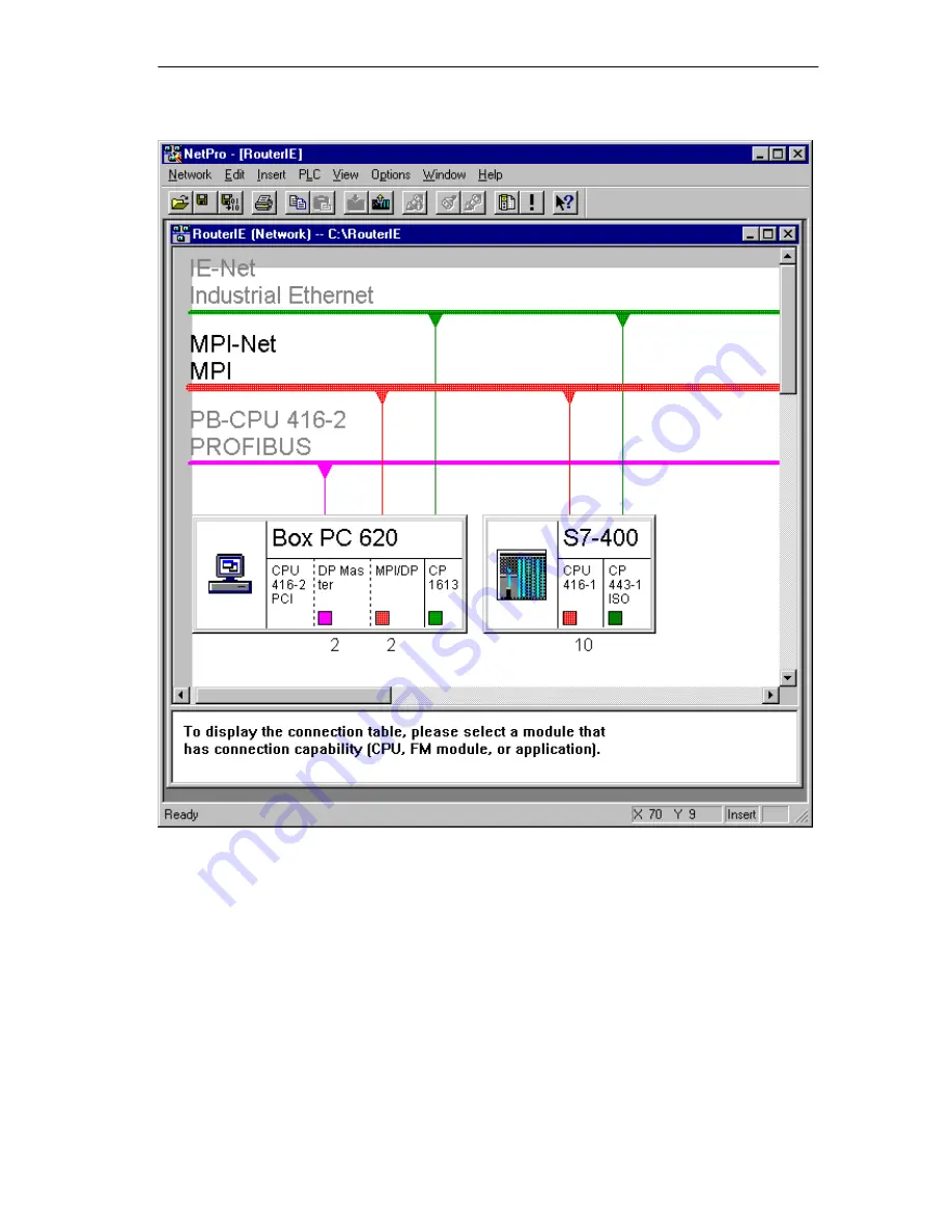
Page 36: ...o open it 4 Double click the CP 1613 node to select it 5 Select IE Net 6 Assign the MAC address 08 00 06 01 00 00 Default address 7 Exit with OK 8 Double click the CPU 443 1 node to select it 9 Select IE Net 10 Assign the MAC address 08 00 06 01 00 01 11 Click OK to apply the settings 12 Double click the DP master of the PC Box 620 to select it 13 Open the interface properties 14 Select a new netw...

Page 37: ...Getting Started 3 9 Windows Automation Center WinAC Slot 412 WinAC Slot 416 Version 3 1 A5E00065531 03 Figure 3 7 Bus Connection ...

Page 38: ... connection in this case an S7 connection Specific properties that depend on the type of the connection whether a connection remains open continuously for example or whether it is established and cleared dynamically in the user program To enter a connection proceed as follows 1 Select the CPU 416 2 PCI module the connection table is visible 2 Double click a blank line in the connection table or se...

Page 39: ...3 Figure 3 8 Creating a Connection 3 In the Station and Module boxes select the programmable module to which the connection is to lead also referred to as a connection partner or remote node 4 Select the connection type S7 connection only in the Type box 5 Select the Open Properties Dialog Box check box ...

Page 40: ...clicking OK The first connection has thus been created The second connection is created in an analogous manner Begin at step 1 with the CPU 416 1 STEP 7 enters the connection in the connection table of the local node and assigns to this connection the local ID and if applicable the partner ID that you require when programming the communication function blocks value for the ID block parameter These...

Page 41: ...ng the Access Point 1 Open the router control panel by selecting the task bar Start Simatic PC Based Control CPU 41x 2 PCI Router Configuration 2 On the Assignment tab press the Set PG PC Interface button Figure 3 10 Setting the PG PC Interface 3 Select the CP1613 CP from the Interface Parameter Assignment Used list box ...

Page 42: ...E00065531 03 4 Select the settings for the corresponding node CP under Properties as in Figure 3 11 Note The station addresses and network related settings must be the same as the settings used in the S7 project Figure 3 11 Setting the CP Properties 5 Terminate the Set PG PC Interface program ...

Page 43: ...nfigured the access points data can be transferred using the router 1 Open the router control panel by choosing the following from the taskbar Start Simatic PC Based Control CPU 41x 2 PCI Router Configuration 2 Start the router by clicking Start The set connections now appear on the Connections router tab 3 1 4 Communications Embed the appropriate communication blocks for example Put Get in your u...

Page 44: ...Getting Started 3 16 Windows Automation Center WinAC Slot 412 WinAC Slot 416 Version 3 1 A5E00065531 03 ...

Page 45: ...k access to the programs on your computer The Tool Manager is configurable You can insert a shortcut icon for any of your programs into the tray You can then access that program from the Tool Manager Section Description Page 4 1 Creating a Toolbar for Easy Access to Your Programs 4 2 4 2 Using the Tool Manager without a Mouse 4 4 4 3 Changing the Language 4 6 4 ...

Page 46: ...ing and dropping into the WinAC Tool Manager Choose Insert from the menu in WinAC Tool Manager refer to Figure 4 2 Note Some shortcut icons for example that of the control panel of the CPU 41x 2 PCI pass command line parameters cmdline To insert a shortcut for these programs you must use Windows Explorer to drag and drop the shortcut onto the WinAC Tool Manager Using the Insert menu command result...

Page 47: ...1 Exit Select the Insert command to display a browser that allows you to insert program icons into the WinAC Tool Manager Click the right button of the mouse to display the WinAC Tool Manager menu Figure 4 2 Inserting Icons into the WinAC Tool Manager Perform the following steps to insert icons into the WinAC Tool Manager 1 Open the WinAC Tool Manager by choosing Start SIMATIC PC Based Control Win...

Page 48: ...ath Name menu command to display the path name for the shortcut icons Select the Rebuild Tool Manager menu command to update refresh the icons for existing program or to remove the icons for programs that have been removed or deleted Pressing F1 or selecting the Help menu command displays the online Help for the WinAC Tool Manager 4 2 Using the WinAC Tool Manager without a Mouse Table 4 1 lists th...

Page 49: ...he WinAC Tool Manager is oriented horizontally not available in Auto Size mode Up arrow or Down arrow Displays the application menu when the WinAC Tool Manager is oriented horizontally Shift Up or Down arrow Moves the WinAC Tool Manager up or down Ctrl Up or Down arrow Moves the WinAC Tool Manager to the top or bottom edge of the screen Alt Up or Down arrow Stretches or shrinks the WinAC Tool Mana...

Page 50: ...the menu or by double clicking the shortcut icon for the WinAC Tool Manager 2 Open the menu in WinAC Tool Manager by right clicking refer to Figure 4 3 3 Choose the Select Language menu option to open the menu in which you can select the language for WinAC refer to Figure 4 3 4 Select the language for WinAC 5 Restart your applications to change the language for the menus and dialog boxes for the W...

Page 51: ...ltiple processes or different computers that cooperate to accomplish a single task jointly DCOM is a set of Microsoft concepts and program interfaces in which client program objects can request services from server program objects on other computers in a network The Component Object Model COM provides a set of interfaces that allow clients and servers to communicate within the same computer runnin...

Page 52: ...C I O I O Siemens button control Third party control cannot be operated simultaneously Figure A 1 Using WinAC Components with DCOM on a Standalone Computer You can also utilize Microsoft s DCOM technology to create a network of computers that cooperate to provide the control system for a machine or process Figure A 2 shows how one computer running an application that uses ActiveX controls from SIM...

Page 53: ... connect to the MPI server using DCOM Third party control Siemens label control Siemens edit control Siemens slider control Siemens button control cannot be operated simultaneously Figure A 2 Using WinAC on Several Computers with DCOM Note You install the WinAC authorization on the server computer you install the SIMATIC Computing authorization on the client computer If you want to run SIMATIC Com...

Page 54: ... other words you cannot use symbol names for the tags in the control engine To use symbol names select the option for connecting via a tag source and browse to a tag file that contains symbols for only one control engine Use the TagFile Configurator to create tag files and connect to control engines using DCOM See the SIMATIC Computing User Manual for information about using STEP 7 and the TagFile...

Page 55: ...de access to the process data SIMATIC Computing provides an OPC server that allows any OPC client application to access data in the control engine SIMATIC Computing does not provide any OPC client application SIMATIC Computing implements the mandatory interfaces as defined in the OPC documentation version 2 0 from the OPC Foundation SIMATIC Computing also implements the IOPC BrowseServerAddressSpa...

Page 56: ... OPC Server C Application X Application Y Figure B 1 Applications Working with Many OPC Servers Your OPC client connects to the OPC server object provided by SIMATIC Computing Due to this connection you can create and edit OPC groups OPC groups structure the data that are accessed You can activate or deactivate a group as a unit or you can subscribe to the list in a group of items so that you can ...

Page 57: ...so SIMATIC Computing Tool Manager 4 1 4 7 connecting distributed applications DCOM A 1 connecting to data via OPC B 2 B 4 connection configuration getting started 3 10 connection table getting started 3 10 contents of the manuals iv control engine OPC access B 2 OPC controls B 2 B 4 control objects OPC server B 2 B 4 control panel 1 1 controls 1 1 courses v CP 1 1 CP assignment getting started 3 5...

Page 58: ...llation errors during installation 2 4 requirements 2 1 WinAC Slot 41x 2 1 insufficient memory errors during installation 2 4 integrating distributed applications DCOM 1 14 1 16 Internet up to date information v K keyboard with Tool Manager 4 4 4 6 M mailbox v manual applicability v S7 400 instruction list iv SIMATIC Computing iv SIMATIC Controls for SIMATIC Computing Version 2 iv WinAC Controllin...

Page 59: ...dsheets sharing data via OPC B 2 STEP 7 Tool Manager 1 16 4 1 4 7 support additional v system requirements 2 1 T technical specifications OLE for Process Control B 1 third party OCX OPC controls B 2 B 4 time synchronization 1 1 1 7 1 10 time of day synchronization service 1 10 Tool Manager 1 16 4 1 4 7 display options 4 4 inserting icons menu commands 4 3 inserting shortcut icons drag and drop 4 2...

Page 60: ...Index Index 4 Windows Automation Center WinAC Slot 412 WinAC Slot 416 Version 3 1 A5E00065531 03 ...

Page 61: ...63 D 92209 Amberg Germany From Your Name Your Title Company Name Street City Zip Code Country Phone Please check any industry that applies to you Automotive Chemical Electrical Machinery Food Instrument and Control Nonelectrical Machinery Petrochemical Pharmaceutical Plastic Pulp and Paper Textiles Transportation Other ...

Page 62: ... take the first available opportunity to fill out this questionnaire and return it to Siemens Please give each of the following questions your own personal mark within the range from 1 very good to 5 poor 1 Do the contents meet your requirements 2 Is the information you need easy to find 3 Is the text easy to understand 4 Does the level of technical detail meet your requirements 5 Please rate the ...

Reviews: