Configuration
5.2 Configuring procedure
1FT2 synchronous motors for SINAMICS S120
Configuration Manual, 03/2021, A5E50645584B AA
61
5.2.3
Define the load case, calculate the maximum load torque and determine
the motor
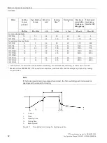
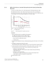
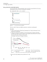
The motors are defined bases on the motor type-specific limiting characteristic curves.
The limiting characteristic curves describe the torque or power curve over the speed.
The limiting characteristic curves take the limits of the motor into account on the basis of the
DC link voltage. The DC link voltage is dependent on the line voltage.
M_max Curve of the maximum torque
S1
S1 characteristic
Figure 5-1
Limit characteristics for synchronous motors
Procedure
1.
Determine the load which is specified by the application.
Use different characteristics for the different loads.
The following operating scenarios have been defined:
–
Duty cycle with constant ON duration
–
Free duty cycle
2.
Determine the characteristic torque and speed operating points of the motor for the defined
load.
3.
Calculate the acceleration torque of the motor.
Add the load torque and the acceleration torque to obtain the maximum required torque.
4.
Verify the maximum motor torque with the limiting characteristic curves of the motors.
The following criteria must be taken into account when selecting the motor:
–
Adherence to the dynamic limits
All speed-torque points of the load event must lie below the relevant limiting
characteristic curve.
–
Adherence to the thermal limits
At average motor speed, the effective motor torque must be below the S1
characteristic (continuous operation) during the load.
You have specified a motor.
❒


