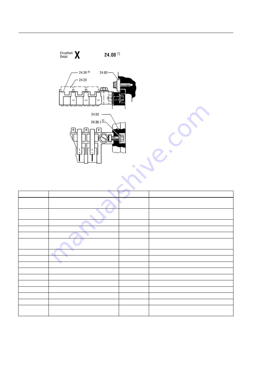
Image 10-3 Detail X brush holder 1G.6 shaft height 160
Table 10-1
Spare parts stator and rotor 1G.6, shaft height 160
No.
Designation
No.
Designation
3.00
Rolling-contact bearing unit, locating
bearing, non-drive end
8.30
Air guide wheel, drive end
4.00
Rolling-contact bearing unit, floating
bearing, drive end
8.30.1
Tare set
5.00
Bearing shield, drive end
8.31
Balancing ring, non-drive end
5.00.1
Rating plate
8.31.1
Tare set
5.41
Louvered cover
8.60
Commutator
6.00
Bearing shield, non-drive end
10.02
Stator frame complete with main and commu‐
tating coil resistors
6.00.1
Set screw
10.16
Grounding connection
6.00.2
Set screw
10.53
Special lifting eye
6.42
Side cover
10.53.1
Sleeve
6.42.1
Seal
20.00
Terminal box
6.44
Top cover
24.00
Brushgear unit, complete
6.44.1
Seal
24.20
Carbon brushes
7.20
Fan impeller, drive end
24.36
Multiple pocket brush holder
7.20.1
Tare set
24.36.1
Fastening screw
7.80
Air baffle plate
24.50
Brush holder (brush rocker, complete)
8.00
Rotor, complete
24.60
Single-acting clamping shoes (clamp straps) for
brush holder
Spare Parts
10.4 Stator and rotor, shaft height 160
SIMOTICS DC 1GG6
108
Operating Instructions 02/2016
Summary of Contents for SIMOTICS DC 1GG6
Page 2: ...08 02 2016 10 27 V4 00 ...
Page 12: ...Table of contents SIMOTICS DC 1GG6 12 Operating Instructions 02 2016 ...
Page 14: ...Introduction 1 1 About these instructions SIMOTICS DC 1GG6 14 Operating Instructions 02 2016 ...
Page 70: ...Commissioning 7 8 Switch off SIMOTICS DC 1GG6 70 Operating Instructions 02 2016 ...
Page 82: ...Operation 8 9 Faults SIMOTICS DC 1GG6 82 Operating Instructions 02 2016 ...
Page 104: ...Maintenance 9 2 Repair SIMOTICS DC 1GG6 104 Operating Instructions 02 2016 ...
Page 138: ...Service and Support SIMOTICS DC 1GG6 138 Operating Instructions 02 2016 ...
Page 142: ...Quality documents SIMOTICS DC 1GG6 142 Operating Instructions 02 2016 ...
Page 153: ......


