● The design of the terminals makes it possible to connect finely stranded conductors without
the use of wire end ferrules.
● Use only wire end ferrules that have been properly crimped onto the conductor so that the
full terminal clamping force holds the conductor in place. Stiff wire end ferrules, which have
not yet been placed under pressure, reduce the binding power exerted on the conductor,
thereby affecting the quality of the contact.
6.6
Connecting the grounding conductor
The grounding conductor cross-section of the machine must match the installation
specifications, e.g. comply with IEC / EN 60204-1.
CAUTION
Damage resulting from protective conductor currents
During motor operation, PE conductor currents of up to 1.7 times the line current can arise if
there is a ground fault on the output side. Neither the PE conductors of normally dimensioned
multi-core connecting cables nor the PE connection points of normal terminal boxes are
suitable for this purpose. This results in material damage.
Install an adequately sized parallel protective conductor and connect this to the ground
terminal on the motor housing. Use only the screws supplied.
Connecting the grounding conductor
A hexagon-head bolt with a spring lock washer and plain washer or a ground terminal is
provided at the designated grounding conductor connection points. The hexagon bolt can be
used for connecting stranded conductors with cable lugs or ribbon cables with an appropriately
shaped conductor end.
When making connections, ensure the following:
● the connecting surface is bare and protected against corrosion using a suitable substance,
e.g. acid-free Vaseline
● the flat and spring washers are located under the bolt head.
● The maximum permissible clamping thickness of 10 mm for the cable lug or strap is not
exceeded
● The minimum required screw-in depth and the tightening torque comply with the values
specified in the tables below. Different values apply to cable lugs or grounding terminals.
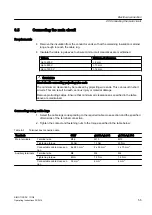
Table 6-3
Tightening torque of screws with cable lugs
Bolt
Screw-in depth
Tightening torque
M12 x 25
> 16 mm
38 Nm
M16 x 35
> 20 mm
92 Nm
Electrical connection
6.6 Connecting the grounding conductor
SIMOTICS DC 1GG6
Operating Instructions 02/2016
57
Summary of Contents for SIMOTICS DC 1GG6
Page 2: ...08 02 2016 10 27 V4 00 ...
Page 12: ...Table of contents SIMOTICS DC 1GG6 12 Operating Instructions 02 2016 ...
Page 14: ...Introduction 1 1 About these instructions SIMOTICS DC 1GG6 14 Operating Instructions 02 2016 ...
Page 70: ...Commissioning 7 8 Switch off SIMOTICS DC 1GG6 70 Operating Instructions 02 2016 ...
Page 82: ...Operation 8 9 Faults SIMOTICS DC 1GG6 82 Operating Instructions 02 2016 ...
Page 104: ...Maintenance 9 2 Repair SIMOTICS DC 1GG6 104 Operating Instructions 02 2016 ...
Page 138: ...Service and Support SIMOTICS DC 1GG6 138 Operating Instructions 02 2016 ...
Page 142: ...Quality documents SIMOTICS DC 1GG6 142 Operating Instructions 02 2016 ...
Page 153: ......

