5.4
Installing the machine
5.4.1
Preparing the assembly area
1. Prepare a suitable assembly area (e.g. assembly stands). Make sure that the assembly area
has sufficient clearance from the floor for the DE shaft end. The necessary data is provided
in the machine dimension drawing.
2. Refer to the shipping documents to check that all motor components are available for
assembly.
5.4.2
Lift the machine to where it will be mounted and position it
• For vertical installation, use all the eyebolts provided and when necessary, hoisting straps
according to DIN EN 1492-1 and/or lashing straps according to DIN EN 12195-2 to stabilize
the position.
• Prevent foreign bodies from falling into the fan cover. For vertical machine installation with
the shaft end facing downwards, attach a protective canopy.
• If the shaft extension is facing upwards, the user must prevent liquid from moving along the
shaft and entering the motor.
• Clean bare metal surfaces with anti-corrosion agent using white spirit to ensure proper
installation and / or machine mounting.
• Do not obstruct the ventilation. Do not draw in the hot discharged air directly – also from
adjacent equipment.
• Avoid exposing them to direct, intense solar radiation, rain, snow, ice, or also dust for
extended periods. Attach a covering structure or an additional cover when using or storing
outdoors.
• Do not exceed the permissible axial and radial forces.
5.4.3
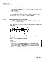
Machines with type of construction IM B15, IM B9, IM V8 and IM V9
Types of construction without bearings on the drive side
These machines do not have their own bearing system for the machine shaft at the drive end
(DE). The machine shaft is accepted by the (hollow) shaft or coupling of the system or driven
machine.
• Using the centering edge, the machine is aligned with respect to enclosures, flanges or
driven machines.
• Note that the temperature of the motor and motor shaft increases during operation. The
thermal expansion of the machine shaft must be compensated by the customer by applying
suitable measures.
Use the spring washers provided to locate the NDE bearing without any play.
Assembly
5.4 Installing the machine
1FZ shaft height 280
Operating Instructions, 02/2022, A5E51698698A
53
Summary of Contents for SIMOTICS DP
Page 2: ......
Page 140: ...Index 1FZ shaft height 280 138 Operating Instructions 02 2022 A5E51698698A ...
Page 141: ......

