Installation
7.2 Installation and removal of the rotor
SIMOTICS M-1FE2 built-in motors
98
Configuration Manual, 05/2021, A5E50494252B AB
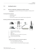
Further devices and tools
•
A fixture for checking the concentricity of the spindle shaft
•
A balancing machine for balancing the rotor (fine or complete balancing)
•
Detergent, e.g. Loctite 7061 or Loctite 7063; screw locking compound, e.g. Loctite 243
The following section only applies to rotors for the asynchronous version.
Mechanical machining of the rotor
Note
Mechanical machining of the rotor in the synchronous version by the customer is not
permissible.
Before mounting the rotor core by shrink-fitting, the inner diameter must be machined to the
shrinkage dimension according to the specifications in the respective dimension sheet.
Shrink-fitting the rotor core generally causes stresses in the spindle shaft. These stresses
cause deformations. For this reason, we recommend re-machining the shaft sections that are
important for the function, e.g. bearing seats, together with the external diameter of the
rotor core.
The shrink-fit rotor core must be machined to the external diameter specified in the
respective dimension sheet.
We recommend machining by grinding.
Summary of Contents for SIMOTICS M-1FE2
Page 1: ......
Page 2: ......
Page 8: ...Introduction SIMOTICS M 1FE2 built in motors 6 Configuration Manual 05 2021 A5E50494252B AB ...
Page 161: ......
Page 162: ......

