Installation
7.2 Installation and removal of the rotor
SIMOTICS M-1FE2 built-in motors
Configuration Manual, 05/2021, A5E50494252B AB
97
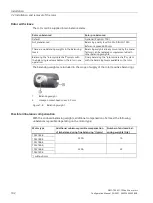
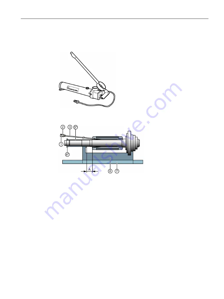
Devices and materials for relieving stress on the rotor with sleeve after installation
•
Oil-pressure hand pump with manometer for relieving the stress on, or removing the rotor
with sleeve for "oil press fit" device version
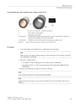
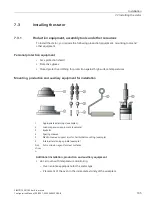
Figure 7-3
Oil pressure hand pump e.g. type SKF 1077454
•
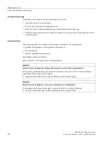
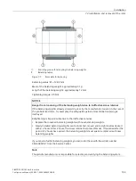
Equipment for relieving stress on the rotor or removing it
Comprising
①
Connection hydraulic hand pump
②
Connector nipple
③
Extension tube, e.g. type SKF1077453
④
Slotted nut (only for relieving stress)
⑤
Spacer sleeve (only for relieving stress)
⑥
Equipment (prism)
1)
⑦
Tray for catching oil made from aluminum, for example
1)
A
Dimension for the axial relative movement for removal of the synchronous version, 90 mm
*
Not required for removal
1)
In the synchronous version these parts must be non-magnetic.
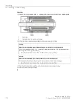
Figure 7-4
Equipment for relieving stress on the rotor with sleeve and for removing it
•
Pressure oil for relieving stress, e.g. SKF LHMF 300 (viscosity 300 mm²/s at 20° C)
•
Pressure oil for removal, e.g. SKF LHDF 900 (viscosity 900 mm²/s at 20° C)
Summary of Contents for SIMOTICS M-1FE2
Page 1: ......
Page 2: ......
Page 8: ...Introduction SIMOTICS M 1FE2 built in motors 6 Configuration Manual 05 2021 A5E50494252B AB ...
Page 161: ......
Page 162: ......


