Mechanical mounting
4.7 Mounting of rotating unions on 1PH8 hollow-shaft motors
1PH808/1PH810 main motors
Operating Instructions, 04/2017, 610.48004.40f
75
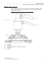
12.Push the intermediate housing with the cutout over the hoses. Screw the intermediate
housing onto the motor. Protect the hoses from mechanical stresses.
13.Screw the fan onto the intermediate housing.
14.Seal the remaining openings between the cutout and the hoses.
4.7.2
Bearingless, frame-supported rotating union
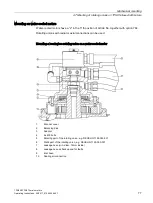
The bearingless frame-supported rotating union cannot be mounted directly on the motor. An
adapter is required for the static part of the rotating union. The adapter is not included in the
scope of delivery and must be made by the customer to match the rotating union to be used.
Please follow the following design instructions:
●
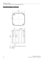
The adapter for holding the static part must be matched to the rotating union to be used.
For this purpose, the dimensions of the manufacturer of the rotating union must be
complied with. The adapter should be designed as shown in Chapter "Suggestion for an
adapter for bearingless, frame-supported rotating unions".
●
The gap between the adapter and the NDE shaft extension in the radial direction must be
as small as possible (approx. 0.25 mm) and be as long as possible in the axial direction
so that exiting coolant cannot penetrate the motor. The leakage connections must be as
large as possible and must be provided at the lowest point in the leakage chamber. The
leakage connection (G3/8") located nearest the static part of the rotating union is for
draining leakage away during operation. The second leakage connection (G1/4") is a
backup for draining away increased leakage due to faults.
NOTICE
Monitoring the backup line
To detect a fault in the rotating union in good time and to protect the motor from flooding,
it is necessary to monitor the flow rate of the backup line.
•
Make sure that a signal is output in the event of leakage.
•
Make sure that the system (coolant supply) is switched off in case of a fault.
Summary of Contents for SIMOTICS M-1PH8
Page 1: ......
Page 2: ......
Page 8: ...Introduction 1PH808 1PH810 main motors 8 Operating Instructions 04 2017 610 48004 40f ...
Page 12: ...Table of contents 1PH808 1PH810 main motors 12 Operating Instructions 04 2017 610 48004 40f ...
Page 148: ...Spare parts 1PH808 1PH810 main motors 148 Operating Instructions 04 2017 610 48004 40f ...
Page 185: ......
Page 186: ......


