Control functions
7.2 General functions
SINAMICS V90, SIMOTICS S-1FL6
Operating Instructions, 04/2019, A5E36037884-007
215
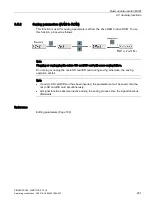
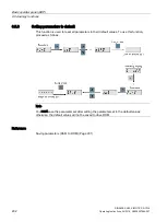
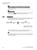
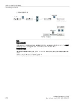
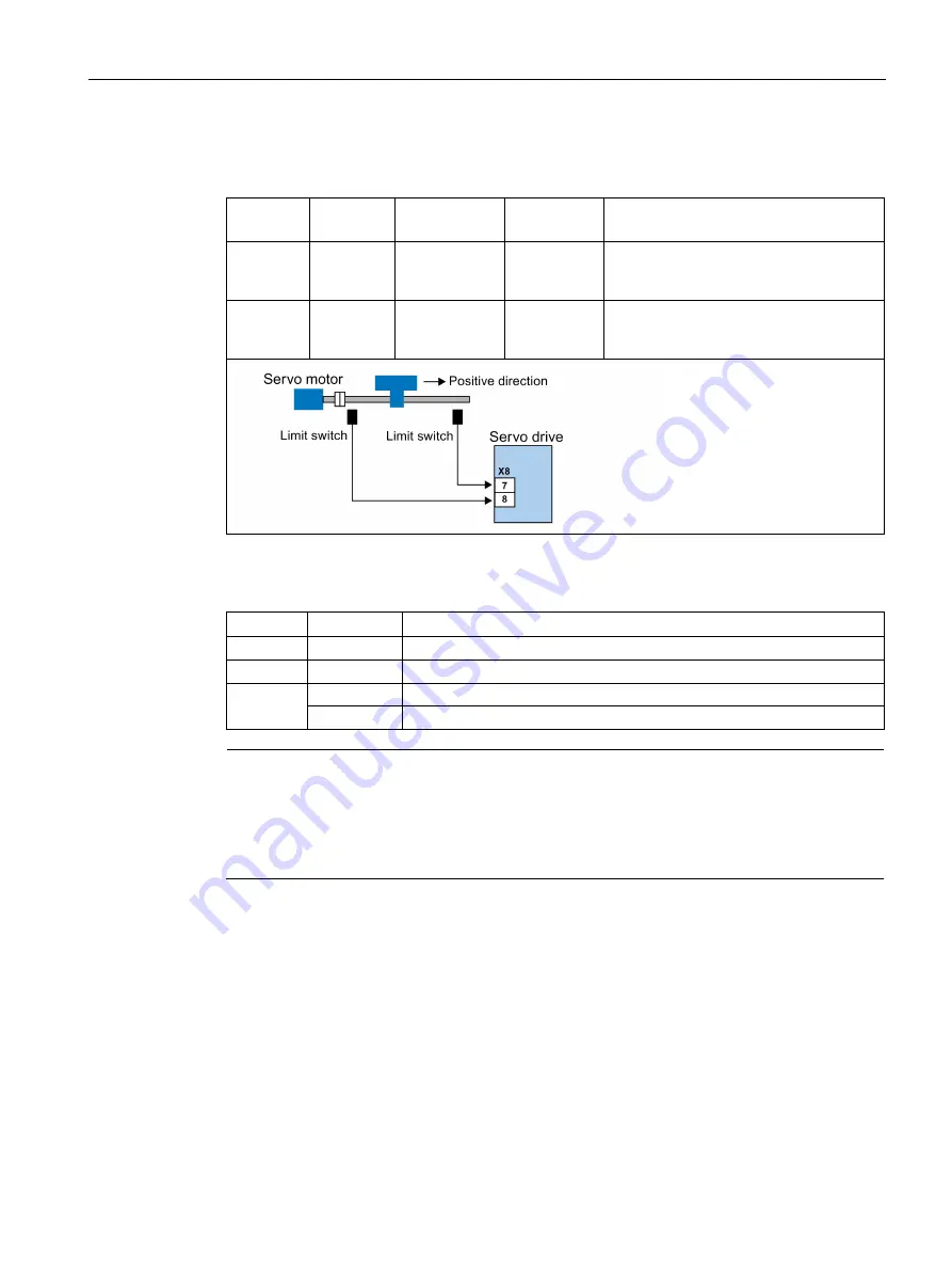
Signal CWL functions as the clockwise travel limit while signal CCWL functions as the
counter-clockwise travel limit. Both of them are level and edge sensitive signals.
Signal type
Signal
name
Pin assign-
ment
Setting
Description
DI
CWL
X8-7 (factory
setting)
Falling edge
(1→0)
The servo motor has travelled to the
clockwise travel limit and has an quick
stop after that.
DI
CCWL
X8-8 (factory
setting)
Falling edge
(1→0)
The servo motor has travelled to the
counter-clockwise travel limit and has an
quick stop after that.
Relevant parameter settings
Parameter Value setting Description
p29303
3
Signal CWL (signal number: 3) is assigned to DI3.
p29304
4
Signal CCWL (signal number: 4) is assigned to DI4.
p29300
bit 1 = 1
Set signal CWL at a high level or rising edge forcedly.
bit 2 = 1
Set signal CCWL at a high level or rising edge forcedly.
Note
DI parameterization
Refer to Section "Digital inputs/outputs (DIs/DOs) (Page 122)" for detailed information about
DI parameterization.
Refer to Chapter "Parameters (Page 341)" for detailed information about parameters.

