Control functions
7.8 Communicating with the PLC
SINAMICS V90, SIMOTICS S-1FL6
280
Operating Instructions, 04/2019, A5E36037884-007
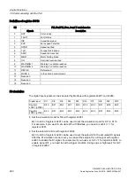
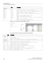
Definition of register 40110
Bit
PTI, Fast PTI, IPos, S and T control modes
Signals
Description
0
RDY
Servo ready
1
FAULT
Fault status
2
INP
In-position signal
3
ZSP
Zero speed detection
4
SPDR
Speed reached
5
TLR
Torque limit reached
6
SPLR
Speed limit reached
7
MBR
Motor holding brake
8
OLL
Overload level reached
9
WARNING 1
Warning 1 condition reached
10
WARNING 2
Warning 2 condition reached
11
REFOK
Referenced
12
MODE 2
In the second control mode
13
Reserved
-
14
Reserved
-
15
Reserved
-
DI simulation
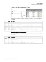
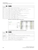
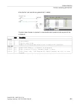
The digital input signals can be simulated by Modbus with registers 40281 and 40283.
Digital input
DI1
DI2
DI3
DI4
DI5
DI6
DI7
DI8
DI9
DI10
Register
40281 (p0795)
Bit 0
Bit 1
Bit 2
Bit 3
Bit 4
Bit 5
Bit 6
Bit 7
Bit 8
Bit 9
Register
40283 (p0796)
Bit 0
Bit 1
Bit 2
Bit 3
Bit 4
Bit 5
Bit 6
Bit 7
Bit 8
Bit 9
●
Set the simulation mode for DIs with register 40281
Bit 0 to bit 9 of register 40281 can be used to set the simulation mode for DI1 to DI 10.
For example, if you want to simulate DI1 with Modbus, you need to set bit 0 = 1 for
register 40281.
●
Set the setpoint for DIs with register 40283
Bit 0 to bit 9 of register 40283 can be used to set the setpoint for the simulated DI signals.
After the DI simulation mode is set, you can set the setpoint for a DI signal with register
40283 to enable the DI signal. For example, if you have set bit 0 = 1 for register 40281, to
enable signal DI1, you need to set the trigger condition (rising edge or high level) for bit 0
of register 40283.


