Interfaces
3.5 Onboard drive interface (C230-2, C240)
SIMOTION C
48
Operating Instructions, 02/2012
Stepper drives
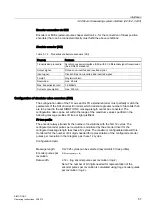
Signals:
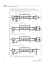
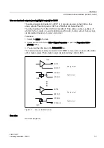
One clock pulse signal, direction signal, and enable signal is provided as a true and negated
signal.
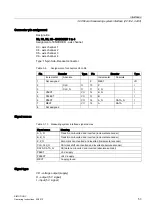
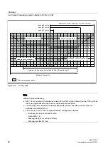
● Setpoint (PULS)
The clock pulses control the motor. The motor performs one step for each rising pulse
edge.
Thus, the number of pulses output determines the angle of rotation, i.e. the distance to be
traversed.
The pulse frequency determines the rotational speed, i.e. the traversing speed.
CAUTION
If your drive unit responds to falling pulse edges, you must replace the true pulse signal
with the negated pulse signal when performing the wiring; failure to do so can cause
deviations to occur between the position calculated by the controller and the actual
position.
● Direction signal (DIR)
The output signal level determines the direction of rotation of the motor.
Signal ON: "Rotation to the left"
Signal OFF: "Rotation to the right"
Note
If the direction of rotation of the motor is different, you can change the direction of rotation
by means of the "Reversal of traversing direction" configuration data element. Refer to
the technical documentation of your drive unit for the correct assignment of the signal
levels to the direction of rotation.
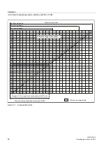
● Enable signal (ENABLE)
This signal is activated when the axis enable is set in RUN mode by the user program.
Signal ON: Power control circuit enabled
Signal OFF: Depending on the power unit, one or more of the following responses can
occur:
– Disable pulse input
– Deenergize motor
– Reset ring counter
– Delete error messages
Note
The ENABLE signal is output at the same time with controller enable contact RF.
Alternatively, you can also use the relay contacts.


