Interfaces
3.6 Onboard measuring system interface (C230-2, C240)
SIMOTION C
Operating Instructions, 02/2012
55
Encoder emulation (incremental shaft encoder (WSG) interface)
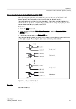
If the drive unit is equipped with encoder emulation, this can be connected instead of an
encoder. The drive control analyzes the information from a rotor shaft angle encoder and
provides information on the actual position to this interface by emulating the signals of an
incremental encoder.
Note
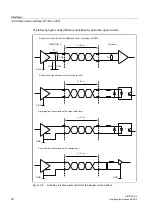
Please note the drive manufacturer's wiring specifications. As the encoder interface of the
C230-2, C240 is non-isolated, it may be necessary to take special measures for EMC on a
case-by-case basis.
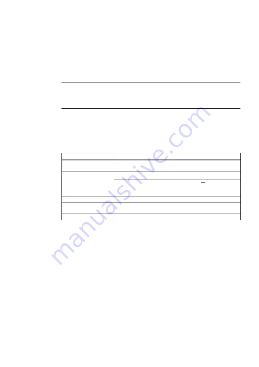
Encoder properties
Incremental encoder
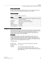
Table 3- 12 Incremental encoder properties
Property
Condition
Transmission procedure:
Differential transmission using 5 V rectangular signals (as in RS422
standard)
Track A as non-inverted and inverted signal
8
D
8
D
Track B as non-inverted and inverted signal
8
D
8
D
Output signals:
Zero signal Z as non-inverted and inverted signal
8
D
8
D
Max. output frequency:
1 MHz
Phase shift of Track A to
Track B:
90° ± 30°
Current consumption:
max. 300 mA


