Interfaces
3.6 Onboard measuring system interface (C230-2, C240)
SIMOTION C
Operating Instructions, 02/2012
57
Encoder connection via EXE
Encoders or EXEs (external pulse shaper electronics - for the connection of linear position
encoders) that can be connected directly must fulfill the above conditions:
Absolute encoder (SSI)
Table 3- 13 Properties of absolute encoders (SSI)
Property
Features
Transmission procedure: Synchronous serial interface (SSI) with 5 V differential signal transmission
(as in RS422 standard)
Output signal:
Data as non-inverted and inverted signal
Input signal:
Clock shift as non-inverted and inverted signal
Format:
Single/multi-turn
Resolution:
max. 25 bits
Max. transmission rate:
1.5 Mbits/s
Current consumption:
max. 300 mA
Configuration of absolute value encoders (SSI)
The configuration data of the TO axis and/or TO external encoder must perfectly match the
parameters of the SSI encoder. Encoders which transmit a greater number of data bits than
are to be read in the set SIMOTION C message length cannot be connected. The
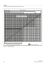
configuration data can be set within the range of the maximum values specified in the
following message profiles (fir tree or right-justified).
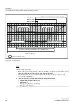
Fir tree profile
The encoder always transmits the number of revolutions with the first 12 cycles. The
configured encoder pulses per revolution is monitored by the encoder driver for the
configured message length less these 12 cycles. The maximum configurable data width is
monitored for the number of bit digits needed for representation of the configured encoder
pulses per revolution in the telegram plus these 12 cycles.
Configuration data:
Message length:
13/21/25 cycles can be selected (asymmetric fir tree profile)
Encoder pulses per
revolution:
≤ 2
(message length -12)
Data width:
≤ 12 + (log encoder pulses per revolution / log 2)
Note: The number of bit digits needed for representation of the
encoder pulses per revolution is calculated using (log encoder pulses
per revolution / log 2).


