Installation
4-67
E
Siemens AG, 2003 All rights reserved
SIMOTION C230-2, 04.2003 Edition
4.2.2
Installing modules on the mounting rail
Accessories
Any accessories you need for installation are in the pack with the modules.
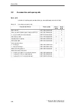
Section 3.6 contains a list of accessories and spare parts, together with the rele-
vant order numbers.
Table 4-3
Accessories for modules
Module
Accessories supplied
Explanation
C230-2
1
slot number plate
For the assignment of slot numbers
2 keys
The key is used to operate the mode selector
for the C230-2.
Labeling plate
For labeling of integrated inputs and outputs
of the C230-2
Signal module
(SM)
1 bus connector
To provide the electrical connections between
the modules
1 labeling plate
To label the inputs and outputs on the module
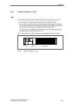
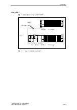
Sequence in which modules are affixed to the mounting rail
1. Power supply module
2. C230-2
3. Signal module(s)
Installation sequence
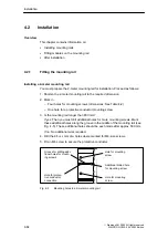
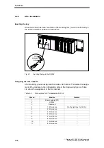
The individual steps for the installation of the modules are described below:
1. A bus connector is included with each signal module, but not with the C230-2.
When inserting the bus connectors, always begin with the C230-2.
Take the bus connector from the next module and plug it onto the C230-2’s bus
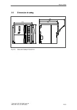
connector (the bus connector is on the back, see Fig. 3-1).
Do not plug a bus link into the “last” module in the line.
2. Fit the modules by hooking them into position, push them against the left-hand
module and lower them down into position.
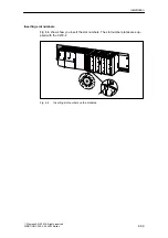
3. Tighten the module fixing screws, applying a torque of 0.8 to 1.1 Nm.
Summary of Contents for SIMOTION C230-2
Page 16: ...Product Overview 1 16 E Siemens AG 2003 All rights reserved SIMOTION C230 2 04 2003 Edition ...
Page 70: ...Installation 4 70 E Siemens AG 2003 All rights reserved SIMOTION C230 2 04 2003 Edition ...
Page 124: ...Commissioning 8 124 E Siemens AG 2003 All rights reserved SIMOTION C230 2 04 2003 Edition ...
Page 130: ...Maintenance 9 130 E Siemens AG 2003 All rights reserved SIMOTION C230 2 04 2003 Edition ...


