Wiring
6-99
E
Siemens AG, 2003 All rights reserved
SIMOTION C230-2, 04.2003 Edition
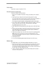
Connection of further actuators/encoders
If you wish to connect further actuators/encoders to the SMs on the P-bus, pro-
ceed in the same way as for connecting digital inputs/outputs to the SIMATIC
S7-300.
See Manual for S7-300 PLCs, M7-300 Module Data.
The digital inputs/outputs on the central I/O system are recorded/output at a re-
fresh rate of approx. 1
ms.
6.3
Connecting shielded cables via a shield connecting
element
Application
With the shield connecting element, you can easily connect all the shielded wires
of the C230-2 or S7 modules to ground – by directly connecting the shield connect-
ing element with the mounting rail.
Design of the shield connecting element
The shield connecting element consists of:
S
A retaining bracket with two threaded studs for connection to the rail (Order
No.: 6ES5 390-5AA00-0AA0) and
S
The shielding terminals
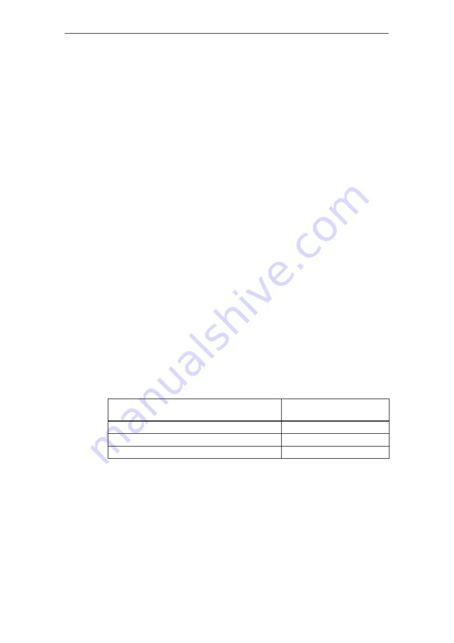
You must use the following shielding terminal, depending on the cable cross sec-
tion used:
Table 6-3
Assignment of cable cross sections and shielding terminals
Wire with shield diameter
Shielding terminal
Order No.:
2 cables, each with 2 to 6 mm shield diameter
6ES7 390-5AB00-0AA0
1 cable with 3 to 8 mm shield diameter
6ES7 390-5BA00-0AA0
1 cable with 4 to 13 mm shield diameter
6ES7 390-5CA00-0AA0
The shield connecting element is 80 mm wide and provides space for two rows,
each with 4 shielding terminals.
Summary of Contents for SIMOTION C230-2
Page 16: ...Product Overview 1 16 E Siemens AG 2003 All rights reserved SIMOTION C230 2 04 2003 Edition ...
Page 70: ...Installation 4 70 E Siemens AG 2003 All rights reserved SIMOTION C230 2 04 2003 Edition ...
Page 124: ...Commissioning 8 124 E Siemens AG 2003 All rights reserved SIMOTION C230 2 04 2003 Edition ...
Page 130: ...Maintenance 9 130 E Siemens AG 2003 All rights reserved SIMOTION C230 2 04 2003 Edition ...

