In this case, the measuring input can transfer up to 2 measured value per 1 ms to the TO (that
is, up to 4 in total). The TO can, however, provide the user program with only the first two
measured values via the system variables measuredValue1 and measuredValue2.
counterMeasuredValue1 and counterMeasuredValue2 are each incremented by "1."
In this case, the error condition is signaled synchronously via system variable error and TO
alarm 40009 is output.
Behavior of the count variables counterMeasuredValue1/2
Lost edges can result in the counters counterMeasuredValue1 and counterMeasuredValue2
diverging.
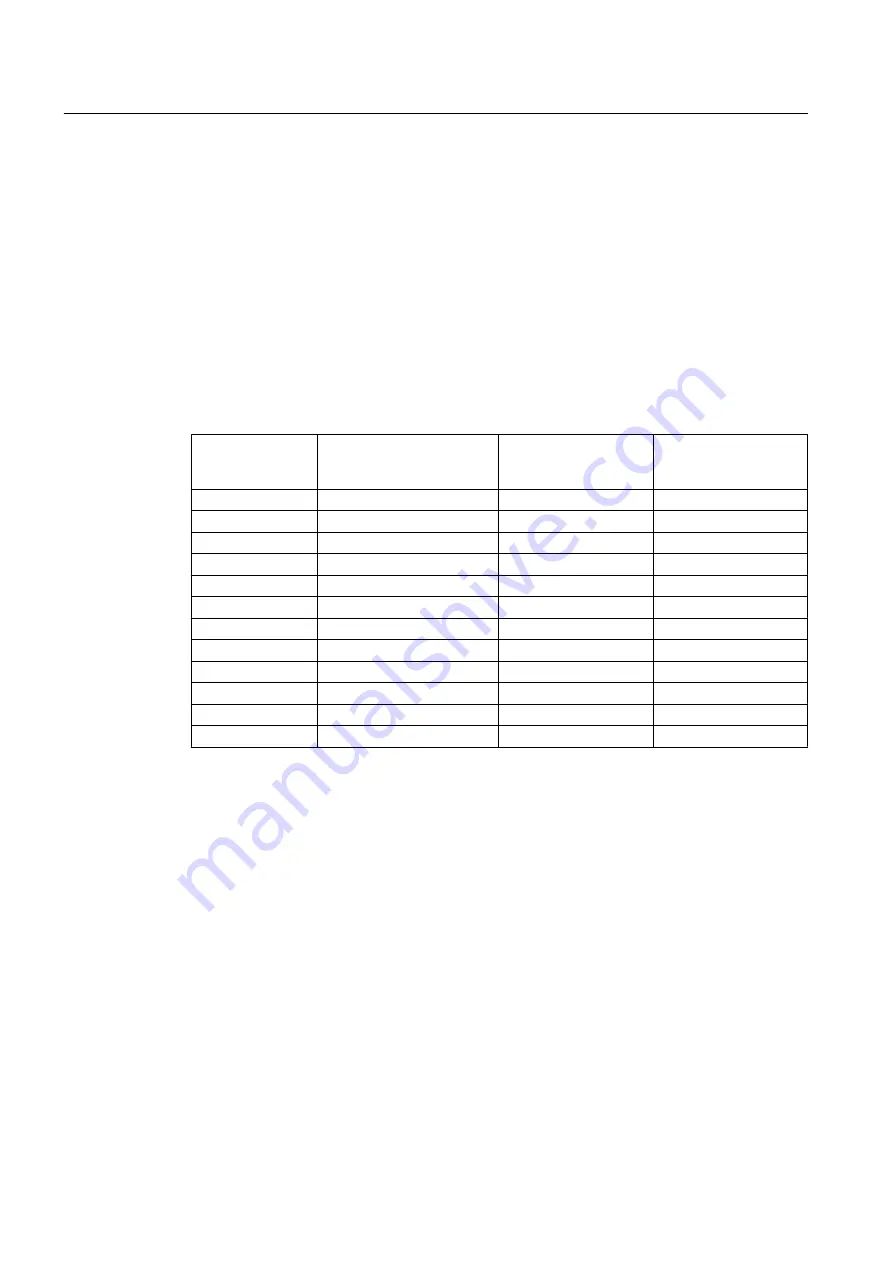
Example: Measurement of rising and falling edges
Processing cycle
clock measuring
input TO
Edges
counterMeasuredValue
1
counterMeasuredValue
2
N
:
:
N+1
6
6
N+2
6
6
N+3
rising-falling
7
7
N+4
rising
8
7
N+5
falling
8
8
N+6
rising-falling-
rising
9
9
N+7
falling
9
10
N+8
rising-falling-
rising
10
11
N+9
falling
10
12
N+10
rising-falling-
rising
11
13
N+11
falling
11
14
*Italics: Edge is lost
Hardware-specific aspects
X142 / Lost Edge Counter
X142 has a counter for lost edges (Lost Edge Counter). Up to 7 lost edges are recorded in
one counter. The counter value is transmitted cyclically and can be symbolically interconnected
in the controller. (LEC). Because the LEC only counts lost edges, for example, only the not
measured "rising" edges are counted in measuring mode "only rising edges."
The LEC only counts the edges that are lost on the X142. Edges lost due to scaling of the
servo cycle clock down to TO processing cycle clock are not acquired by the LEC.
The edges lost on the measuring equipment are only signaled via the LEC. That is, they are
not signaled via system variable/TO alarm.
Via an I/O variable, it is possible to access LEC symbolically and evaluate it in the user program.
Measuring Input TO - Part III
5.2 Fundamentals of Measuring Input technology object
Output Cams and Measuring Inputs
146
Function Manual, 04/2014

