background image

Product Description

02.2001

SIMOLINK Pulse Generator

GWE-477 764 4070.76 J 

Siemens AG

2-2

Operating Instructions

SIMOVERT MASTERDRIVES

2.1 

Description of function

The incoming optical signals from the fiber-optic cable are converted to
electrical signals by means of fiber optic receivers on all SIMOLINK
modules and then transferred to the fiber-optic transmitter where they
are converted back to optical signals. The propagation delays caused
by this process are calculated while SIMOLINK is booting and the dead
times compensated accordingly for active SIMOLINK nodes. The
receive information is derived, depending on parameterization, from the
buffered, electrical signals and transferred with the SYNC interrupt (last
telegram in SIMOLINK polling). The transmit information of the node is
transferred in the opposite direction and written to the associated
telegrams (electrical signals).

The SIMOLINK Pulse Generator is incorporated in the SIMOLINK ring
like a SIMOLINK slave; it is an active node and included in the dead-
time calculation. However, it does not have its own node address and
cannot therefore write transmit telegrams to the SIMOLINK (SLP does
not supply a return value).

The SIMOLINK receive address (0 ... 200; dispatcher mode: Address of
node which is sending the speed setpoint) is set via the DIL switches
on the front panel. The momentary speed setpoint is read in the
MASTERDRIVES 32-bit format (4000 0000 hex = 100 %) from channel
0. Only the 10 highest bits are resolved with a maximum output of
112 %, resulting in a speed resolution of 0.4 %. The speed setpoint
must be updated (new setpoint or identical value if velocity is constant)
in every SIMOLINK cycle by the transmitting node.

The speed setpoint is transferred to the frequency generator with the
SYNC interrupt which then generates the equivalent frequency with the
correct phase sequence of the two output signals (tracks A and B). An
output frequency of 25 kHz corresponds to a speed setpoint of 100 %.
Alternatively, a jumper can be inserted in the mating connector of X2 to
activate the "100 kHz signal" operating mode. The frequency generator
can then output signals from 0 to 100 kHz. In this mode, the frequency
signal is output via track A and the sign (direction of rotation) via track
B. The sign is a static 0 (positive) or 1 (negative) signal.

The RS422 interface forms the desired signal levels which can be
picked off on SUB D socket X2.

The operating states are indicated by the three LEDs on the housing
front panel.

Summary of Contents for SIMOVERT MASTERDRIVE Series

Page 1: ...SIMOVERT MASTERDRIVES Betriebsanleitung Operating Instructions SLP SIMOLINK Puls Generator SLP SIMOLINK Pulse Generator Ausgabe Edition AA GWE 477 764 4070 76 J ...

Page 2: ...emens The reproduction transmission or use of this document or its con tents is not permitted without express written authority Offenders will be liable for damages All rights including rights created by patent grant or registration of a utility model or design are reserved We have checked the contents of this document to ensure that they coincide with the described hardware and software However d...

Page 3: ...ARNINGS 1 1 2 PRODUCT DESCRIPTION 2 1 2 1 Description of function 2 2 3 TECHNICAL DATA 3 1 4 INSTALLATION 4 1 4 1 EMC measures 4 1 4 2 Housing 4 1 5 CONNECTIONS 5 1 5 1 Connector X1 5 1 5 2 Encoder interface X2 5 2 5 3 Fiber optic cable connection 5 5 6 START UP 6 1 6 1 Setting the DIL switch 6 1 6 2 LED displays 6 2 6 3 SIMOLINK data interface 6 3 ...

Page 4: ......

Page 5: ...an imminently hazardous situation which if not avoided will result in death serious injury and considerable damage to property indicates a potentially hazardous situation which if not avoided could result in death serious injury and considerable damage to property used with the safety alert symbol indicates a potentially hazardous situation which if not avoided may result in minor or moderate inju...

Page 6: ...reful operation and maintenance This documentation does not purport to cover all details on all types of the product nor to provide for every possible contingency to be met in connection with installation operation or maintenance Should further information be desired or should particular problems arise which are not covered sufficiently for the purchaser s purposes the matter should be referred to...

Page 7: ... come into contact with highly insulating materials e g plastic parts insulated desktops articles of clothing manufactured from man made fibers Boards must only be placed on conductive surfaces Boards and components should only be stored and transported in conductive packaging e g metalized plastic boxes or metal containers If the packing material is not conductive the boards must be wrapped with ...

Page 8: ......

Page 9: ...ntrolled main drives is implemented by means of SIMOLINK and MASTERDRIVES Motion Control drives The SIMOLINK Pulse Generator uses a speed setpoint transported via SIMOLINK to generate two pulse signals in quadrature of proportional frequency 100 25 kHz These are supplied to further devices via the RS422 EIA422 standard The frequency output corresponds to that of a pulse encoder with 1000 pulses re...

Page 10: ...he SIMOLINK SLP does not supply a return value The SIMOLINK receive address 0 200 dispatcher mode Address of node which is sending the speed setpoint is set via the DIL switches on the front panel The momentary speed setpoint is read in the MASTERDRIVES 32 bit format 4000 0000 hex 100 from channel 0 Only the 10 highest bits are resolved with a maximum output of 112 resulting in a speed resolution ...

Page 11: ...n operation Cooling method operation Convection Permissible ambient or coolant temperature In operation In storage During transportation 0 C to 55 C 25 C to 70 C 25 C to 70 C Permissible humidity rating Transport storage In operation Relative air humidity 95 85 condensation not permitted Power supply Rated supply voltage DC 24 V 20 4 V to 28 8 V Power consumption Approx 140 mA Encoder interface Tr...

Page 12: ......

Page 13: ...top hat rail The ground connection between the rail and the equipotential bonding conductor must be made by the end user during installation For further information please refer to Chapter Instructions for Design of Drives in Conformance with EMC Regulations of the SIMOVERT MASTERDRIVES Compendium Motion Control Order No 6SE7087 6QX50 4 2 Housing The following diagrams show a schematic illustratio...

Page 14: ...Installation 02 2001 SIMOLINK Pulse Generator GWE 477 764 4070 76 J Siemens AG 4 2 Operating Instructions SIMOVERT MASTERDRIVES RX TX M 24 V X1 RX TX View from below Plan view Fig 4 2 ...

Page 15: ...tion with one transmit socket and one receive socket 5 1 Connector X1 The 6 pin connector is on top of the housing The 24 V power supply to the SIMOLINK Pulse Generator is connected via X1 M 24 V Connector Socket X1 Fig 5 1 Terminal Designation Meaning Range 1 Unused 2 Unused 3 Unused 4 Unused 5 M Ground 6 24V 24 V power supply 21 28 V Connectable cross section 1 5 mm2 AWG 16 Terminal 1 is the ter...

Page 16: ...uency generator A A B B SEL_100 kHz GND P5 2 7 4 9 1 3 8 Fig 5 2 Schematic of output circuit connector X2 The two operating modes 90 pulses and 100 kHz signal are selected via a jumper in the encoder connector The 90 pulses setting is the default and is activated when pin 1 in the encoder interface is unused Pin Signal Meaning for 90 pulses Range 2 A Track A not inverted RS422 7 A Track A inverted...

Page 17: ...nd see below jumper to GND 5 6 n c Unused Housing Outer shield 9 pin SUB D socket with screw locking mechanism UNC Table 5 3 Assignment of connector X2 for 100 kHz signal mode To maintain immunity to interference a shielded cable must be used and the shield attached in the connector housing One or several drives devices can be connected to the SLP module When the SLP is operated in conjunction wit...

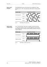
Page 18: ...t Track A Track B Negative setpoint Track A Track B Fig 5 3 Signal shape in 90 pulses mode In the 100 kHz signal mode track A outputs 4 times the frequency i e 100 kHz correspond to 100 Track B supplies the sign according to the following rule The signal is low for positive setpoints and high for negative setpoints Setpoint input Signal shape at output Positive setpoint Track A Track B Negative se...

Page 19: ...X The transmit socket is light gray and labeled TX The following Hewlett Packard fiber optic modules are installed in the SIMOLINK Pulse Generator Transmitter HFBR 1528 Receiver HFBR 2528 Plastic or glass fiber optic cables can be used Depending on the type of cable selected the inter node distances are as follows Max 40 m between each node in the case of plastic cables or Max 300 m between each n...

Page 20: ...7 ì Once the top half of the connector is latched into the lower half the cable is lodged securely in the connector 5 Use a sharp knife to cut the protruding end of the cable almost flush with the connector surface Cut at right angles to the fiber optic cable axis 6 You now need to polish the surface of the fiber optic To do this place the end of the sleeve flat on the surface of the matt rough si...

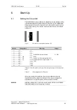
Page 21: ...read address address 75 Switch Designation Meaning Range 1 2 0 1 2 2 1 2 3 2 2 4 4 2 3 8 5 2 4 16 6 2 5 32 7 2 6 64 8 2 7 Channel 128 SIMOLINK receive address Note Switch 1 is the least significant bit Switch position on right means 1 or ON 0 200 Channel 1 of the DIL switch is at the top of the housing front panel in the assembled state Table 6 1 Value assignments for DIL switch When set via the D...

Page 22: ...rectly set SIMOLINK receive address higher than 200 set alternate flashing of SYNC and FREQ LEDs l l SYNC interrupt is being received Setpoint 0 or 0 Hz output frequency or setpoint telegram is not being received l l l FREQ LED flashes at the output frequency Setpoint telegram is being received and setpoint not equal to 0 flashing is perceptible at very low setpoints only LED off l LED illuminated...

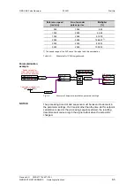
Page 23: ...tor has a frequency range of 0 Hz to 112 kHz at a rated frequency of 100 kHz In the 90 pulses mode 4 edges required for correct signal sequence from tracks A and B the resulting rated output frequency per track is 25 kHz and a maximum possible setpoint output of approximately 112 32 bit setpoint hex Setpoint Output frequency in 90 pulses mode kHz Frequency in 100 kHz sign mode 47C0 0000 112 1 28 0...

Page 24: ...in If the generator is to simulate shaft encoders with other pulse numbers per revolution or different speed normalization the setpoint to the SLP must be renormalized This can be done for example by multiplying the machine setpoint In this regard it is important to note that the maximum setpoint for the SLP on the SIMOLINK data interface must not exceed 112 max output frequency of approximately 2...

Page 25: ...lier in U014 F 0 000 U951 31 04 20 KK0470 K 571 U110 0 01 y K 414 02 x1 x2 100 x1 x2 KK0571 Speed setpoint for virtual master axis from ramp function generator P751 1 0 KK470 SLB transmit data P751 2 0 KK470 U961 31 X n U961 51 X U951 51 04 20 Fig 6 4 Example of setpoint normalization parameter settings The processing time slot and sequence must be taken into account in the parameter settings If a...

Page 26: ...3 02 2001 2 Produktbeschreibung Erstausgabe 2 02 2001 3 Technische Daten Erstausgabe 1 02 2001 4 Montage Erstausgabe 2 02 2001 5 Anschließen Erstausgabe 6 02 2001 6 Inbetriebsetzen Erstausgabe 5 02 2001 The following editions have been published so far Edition Internal Item Number AA GWE 477 764 4070 76 J AA 76 Version AA consists of the following chapters Chapter Changes Pages Version date 1 Defi...

Reviews: