SIMOLINK Pulse Generator
02.2001
Installation
Siemens AG
GWE-477 764 4070.76 J
SIMOVERT MASTERDRIVES
Operating Instructions
4-1
4 Installation
The SIMOLINK Pulse Generator module is snapped onto an EN 50022-
compliant TS 35 top-hat rail. The requisite mechanical mounting
elements are fitted in the housing.
4.1 EMC
measures
The module is connected to ground via the top-hat rail. The ground
connection between the rail and the equipotential bonding conductor
must be made by the end-user during installation.
For further information, please refer to Chapter "Instructions for Design
of Drives in Conformance with EMC Regulations" of the SIMOVERT
MASTERDRIVES Compendium Motion Control, Order No.:
6SE7087-6QX50.
4.2 Housing
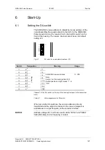
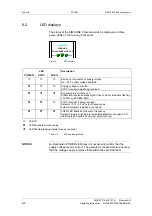
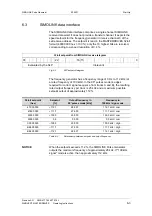
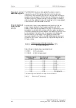
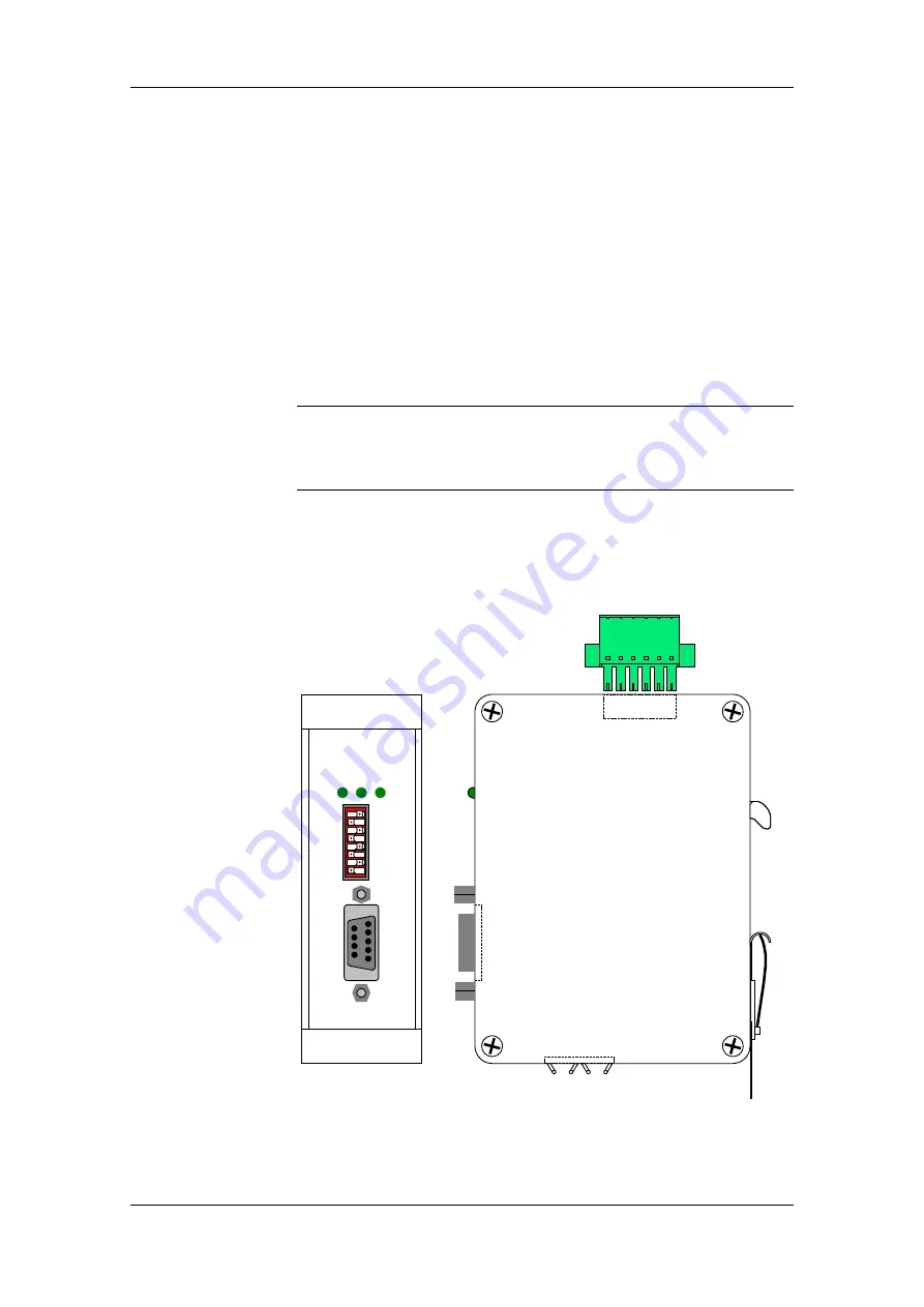
The following diagrams show a schematic illustration of the housing
and the layout of connections and operating elements.
SIMOLINK
PULS GENERATOR SLP
POWER
SYNC
FREQ
X2
2
0
2
7
ON
KA
N
A
L
Front view
Side view
Fig. 4-1
NOTE


