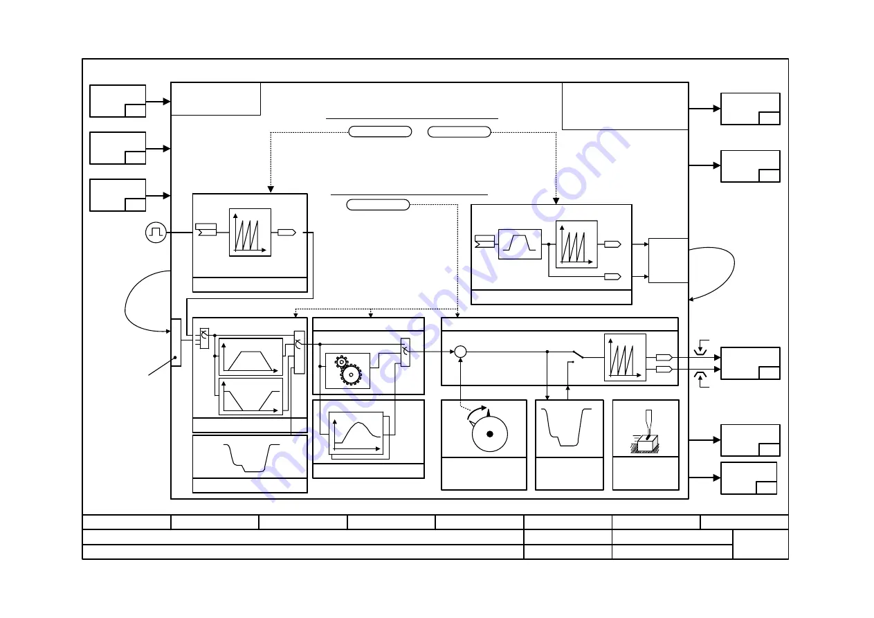
Function diagram
8
7
6
5
4
3
2
1
fp_mc_831_e.vsd
Technology option
MASTERDRIVES MC
23.10.02
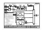
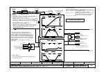
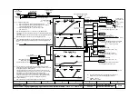
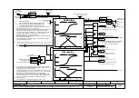
Synchronism operating mode (overview)
- 831 -
Positioning input signals
Control bits
[809]
Synchronism operating mode
[RST] Reset technology
[FUM]
Follow-up mode
[STA] Start synchronism
11 = Synchronism operating
mode
Real master value
[sheet 833] Real master
s*
Position signals
[815]
Mode
[809]
[Sheet 835] Electr. gearbox
1:1
[FUNCTION]
[Sheet 836] Generation of position setpoint
+
+
s*
v*
Sampling time for synchronism [sheet 834...843]:
U953.33 = 20 ==> Synchronism as
positioning mode inserted in the
sampling time U953.32
U953.33<20 ==> Synchronism
operates as an autonomous free
block (recommended: U953.33=4)
Only permitted if positioning modes
are deactivated (i.e. if U953.32=20)
U953.33<4 is illegal!
Master value
[Sheet 841] Synchro-
nization, displace-
ment angle adjustm.
[Sheet 839] Cam
y
x
x
y
s
[Sheet 837]
Catch-up
v
0
[Sheet 843]
Position correc.
referencing
<1>
MD13
MD12
s
t
SIMOLINK
transmit
channel
[Sheet 832] Virtual master axis
s
t
Ramp-function generator
Virtual master value
s*
v*
[160]
s
t
Sampling time for real master and virtual master axis:
Recommended: U953.31/ 34=4 (use
same time slot as for synchronism!) The
real and virtual master axes are dedicated
autonomous free blocks.
Diagnostic data
[818]
[FUR]
Processing running
[FWD] Forwards
[BWD] Backwards
[FUR_M] Virtual master running [832.6]
[ARFD] Axis is referenced [843.8]
Positioning output signals
Master value of
virtual master axis
SIMOLINK-
receive
channel
[150]
<1> Software limit switch
with linear axis
Status bits
[811]
Control signals
for position
sensing
[815]
Setpoints
[817]
[Sheet 837] Catch-up
[OPERATION]
Engaging
v
s
v
s
Disengaging
[Sh.834] Engaging/diseng.
v
0
Synchronism
status
bits
[846]
V2.5
<2>
<2> Setpoint for master value synchronization
U953.33 = ___(20)
U953.31 = ___(20)
U953.34 = ___(20)


