08.2012
Technology Option F01
Siemens AG
6SE7087-6QX70 (Version AN)
SIMOVERT MASTERDRIVES
Compendium Motion Control
9-7
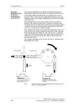
The figure shows a typical application for an NC program running
automatically on the MASTERDRIVES MC. A chip board, which is
laminated on both sides, is drilled in the following sequence of NC
program steps:
♦
Travel A
→
B: The drill support travels in rapid traverse until just
before the material and starts to reduce the
feedrate. At exactly point B, the drill reaches the
reduced feedrate for drilling through the laminated
plastic.
♦
Travel B
→
C: Slow drilling of the laminate
♦
Travel C
→
D: The actual chip board is drilled at the normal
feedrate.
♦
Travel D
→
E: The reduced feedrate is applied again for the lower
layer of laminate.
♦
Travel E
→
A: The drill returns at increased velocity.
The NC program input on the MASTERDRIVES MC is also listed in the
figure above.
9.3.3
Synchronization
The following synchronization functions are included:
♦
Electronic shaft (angle-synchronous, long-term stable
synchronization of several axes)
♦
Electronic gearbox (with sensitive transmission ratio adjustable via
numerator and denominator; value range for numerator and
denominator -32767 ... +32767)
♦
The transmission ratio can also be changed during operation. If
necessary, the defined transmission ratio can be controlled via a
free ramp-function generator [791] to prevent jumps.
♦
Electronic cam
•
"Table synchronization" with up to 400 interpolation points on the
MASTERDRIVES MC. The 400 interpolation points can be
distributed variably among one to eight tables. One table can be
reloaded in the background while the other is running online. The
interpolation between the points is linear.
•
The interpolation points do not have to be equidistant, but can be
arranged closer to each other in critical zones and further away
in linear areas.
•
Table change on-the-fly possible during operation
•
The table is scalable in the X and Y directions, and has an
integrated gearbox
General
synchronization
functions [831]


