Technology Option F01
08.2012
6SE7087-6QX70 (Version AN) Siemens AG
9-76
Compendium Motion Control
SIMOVERT MASTERDRIVES
9.4.28
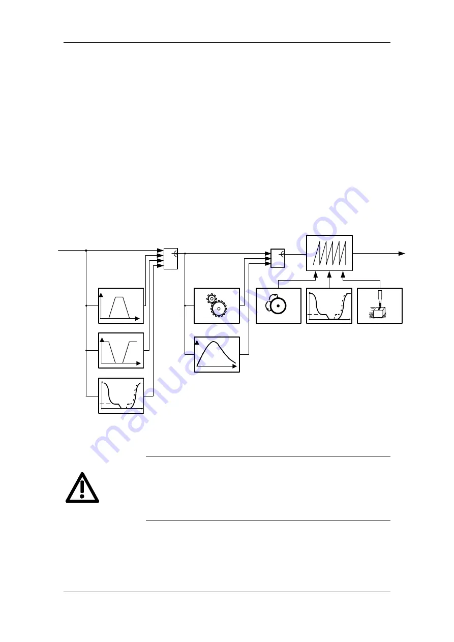
Synchronization mode - overview [831]
Sheet [831] shows an overview of the synchronization functions, their
interconnection, and the detailed representation of the functions on
sheets [832...846] of the function diagram.
You will find detailed information on synchronization mode in the
"Synchronization functions" chapter in the Function Description
of manual /1/.
In the interest of the smallest possible deadtime differences, it is
strongly recommended to use the virtual master axis as the master
value source. An external master value generator ("real master axis",
e.g. master pulse generator installed on the front section of the
machine) should only be used in exceptional circumstances.
Synchronization mode includes the following functions:
Δ
2
1
0
3
Start
Stop
Catch-up
Gear function
Curve cam
Synchronization
offset input
Catch-up
Position correction
referencing
Position setpoint
generation
1:1 Continuous
Output
Continuous operation
Function
Mode
Input
2
1
0
Fig. 9-29
By making an appropriate selection of master setpoint and
synchronization parameters make sure that no inadvertent axis
accelerations can occur.
Position setpoint jumps as a result of control intervention or parameter
changes during running operation can occur both at the input and the
output of synchronism.
CAUTION


