


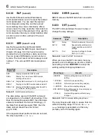


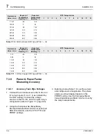
7
Commissioning
SIMPRO-100
100
PRIM-2400C
3. Apply ac or dc control power to the relay.
Within a moment of energizing the relay, the
green enable LED (Relay Enabled) on the
front panel should illuminate, and the relay
self-test ALARM b-contact (B17, B18) should
open.
4. Connect the PC to the relay using the
appropriate serial cable (SIM-232 or a
null-modem cable). Start the PC and terminal
emulation software or SIMPRO-PC software.
Establish communication with the relay at
Access Level 1. Refer to Chapter 6, page 85
for more information on serial port
communications. Refer to Chapter 3, page 39
for more information on the SIMPRO-PC
Software. Enter Access Level 2 using the
factory default password, 100.
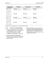
Hint:
Use the HELP command at any Access
Level to get a list of available serial port
commands.
5. Using the front-panel Set Relay\Date and Set
Relay\Time functions or serial port DATE and
TIME commands, set the correct relay clock
time and, if necessary, date.
6. Using the front-panel Set Relay\Password or
serial port Access Level 2 PASSWORD
command, enter your new Access Level 2
password. Be sure to record the new
password in a safe location.
7. Using the SIMPRO-PC software or the SET,
SET R, and SET P commands, enter relay
settings according to the Settings Sheets for
your application. If you are using the
SIMPRO-PC software, you can use it to
develop, store, and transfer settings to the
SIMPRO-100 Relay (see Chapter 3, page 39
for more details).
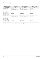
8. If you are using a SIMPRO-100-RTD External
RTD Module, connect the fiber-optic cable to
the module fiber-optic output. At the relay-end
of the fiber, you should be able to see a red
light that indicates the module is sending
data. Plug the relay-end of the fiber into the
relay fiber-optic receiver input.
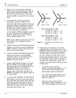
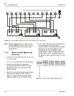
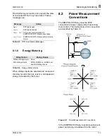
Figure 7.1
Three-Phase AC Connection Test
Signals
9. Verify relay ac connections. Connect the
protective relay ac test signal source to the
SIMPRO-100 Relay through the motor control
center wiring. (You may connect directly to
the relay; however, this does not verify the
accuracy of the wiring in the motor control
center.) Apply rated ac current (1 A or 5 A) to
the relay phase current inputs. If the relay is
equipped with voltage inputs, apply rated
voltage for your application to the relay phase
voltage inputs.
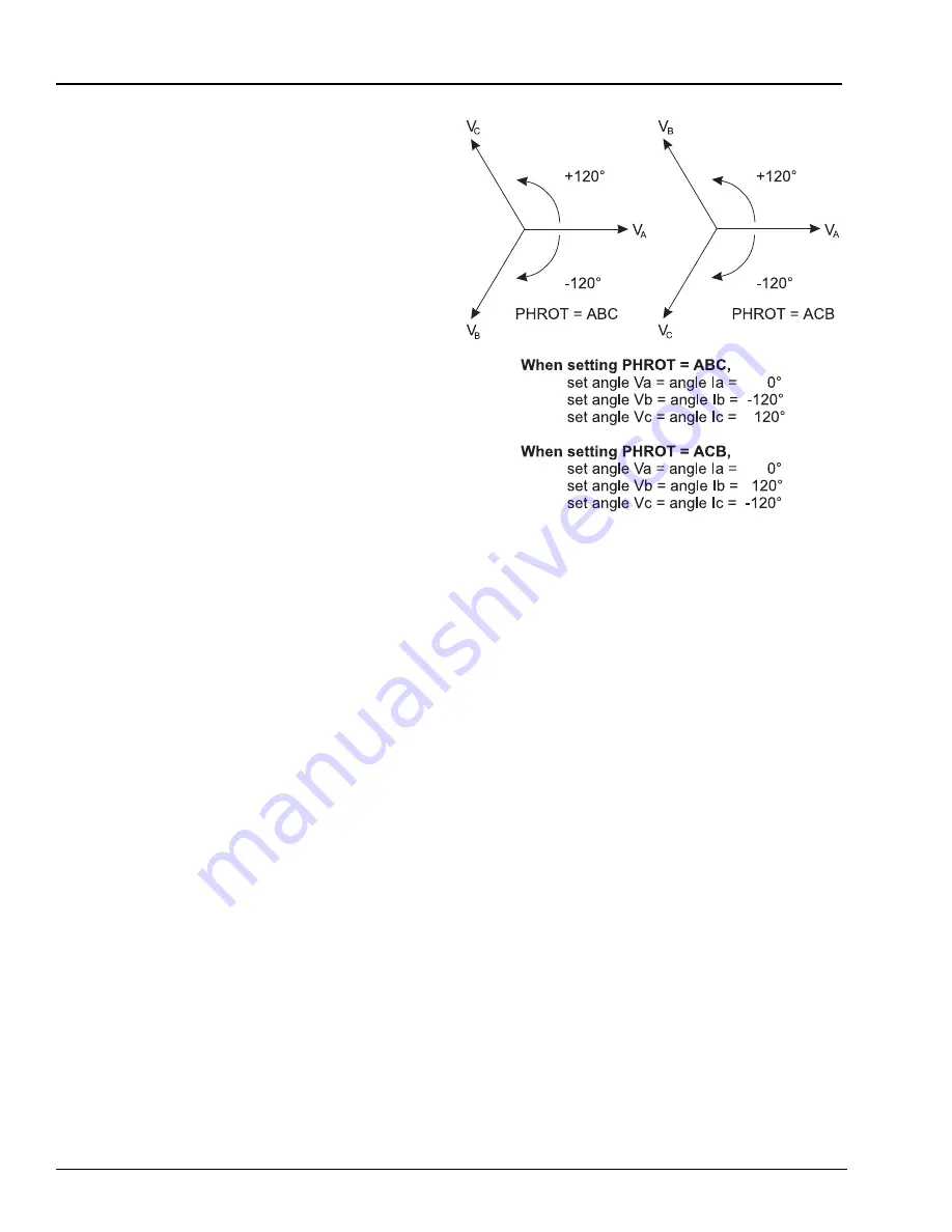
•
If you set the relay to accept
phase-to-neutral voltages (DELTA_Y = Y),
set the current and/or voltage source
phase angles as shown in Figure 7.1.
•
If you use open-delta potentials, set the
test source phase angles as shown in
Figure 7.2, page 101.
•
When you set the relay to accept
single-phase voltage (SINGLEV = Y), you
can connect and apply VA or VAB only.
Summary of Contents for SIMPRO-100
Page 1: ...SIMPRO 100 Motor Protection Relay Instruction Manual Document No PRIM 2400C ...
Page 12: ...Contents SIMPRO 100 x PRIM 2400C ...
Page 16: ...Contents SIMPRO 100 xiv PRIM 2400C ...
Page 42: ...3 SIMPRO PC Software SIMPRO 100 40 PRIM 2400C ...
Page 100: ...6 ASCII Serial Port Operation SIMPRO 100 98 PRIM 2400C ...
Page 127: ...SIMPRO 100 Event Analysis 9 PRIM 2400C 125 Figure 9 2 Example SER Report ...
Page 136: ...10 Maintenance Troubleshooting SIMPRO 100 134 PRIM 2400C ...
Page 138: ...A Firmware Versions SIMPRO 100 136 PRIM 2400C ...
Page 206: ...D SIMPRO PC Compatibility Features SIMPRO 100 204 PRIM 2400C ...
Page 214: ...E Motor Thermal Element SIMPRO 100 212 PRIM 2400C ...
Page 230: ...F SIMPRO 100 Relay Settings Sheets SIMPRO 100 228 PRIM 2400C ...
Page 239: ......


