


SIMPRO-100
Commissioning
7
PRIM-2400C
101
•
Use the front-panel Meter
Values\Instantaneous Meter function or
serial port METER command to verify that
the relay is measuring the magnitude and
phase angle of both voltage and current
correctly, taking into account the relay
PTR and CTR settings and the fact that
the quantities are displayed in primary
units. This step verifies the signal polarity
and per-phase ac connections to the
relay.
•
Apply rated ac current (1 A or 5 A) to the
relay IN input if used. Use the front-panel
or serial port METER function to verify
that the relay is measuring current
magnitude and phase angle correctly,
taking into account the relay CTRN setting
and the fact that the quantities are
displayed in primary units.
10. Verify contact input connections. Using the
front-panel View Relay Word\Row 10
function, check the contact input status in the
relay front-panel display. As you short-circuit
each input, its label (IN1, IN2, IN3, etc.)
should appear in the front-panel display.
11. Verify relay contact output electrical
performance using the front-panel Pulse Out
Contact\TRIP command to close the TRIP
output contact. Repeat for the other output
contacts. Make sure that each contact
operates properly in its designated
annunciation, control, or tripping circuit. See
Chapter 5, page 75 and Chapter 6, page 85
for more details regarding the PULSE
command.
12. Perform any desired protection element tests
using the individual element test procedures
found in Section 7.3, page 103. Only perform
enough tests to prove that the relay operates
as intended; exhaustive element performance
characterizations are not necessary for
commissioning.
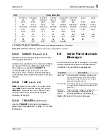
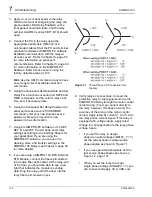
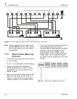
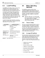
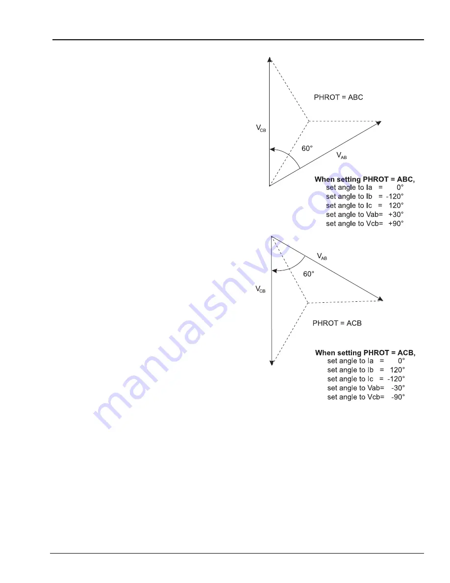
Figure 7.2
Open-Delta AC Potential Connection
Test Signals
13. Connect the relay for tripping duty. Verify that
any settings changed during the tests
performed in step 12. have been changed
back to their correct values for this
application.
Summary of Contents for SIMPRO-100
Page 1: ...SIMPRO 100 Motor Protection Relay Instruction Manual Document No PRIM 2400C ...
Page 12: ...Contents SIMPRO 100 x PRIM 2400C ...
Page 16: ...Contents SIMPRO 100 xiv PRIM 2400C ...
Page 42: ...3 SIMPRO PC Software SIMPRO 100 40 PRIM 2400C ...
Page 100: ...6 ASCII Serial Port Operation SIMPRO 100 98 PRIM 2400C ...
Page 127: ...SIMPRO 100 Event Analysis 9 PRIM 2400C 125 Figure 9 2 Example SER Report ...
Page 136: ...10 Maintenance Troubleshooting SIMPRO 100 134 PRIM 2400C ...
Page 138: ...A Firmware Versions SIMPRO 100 136 PRIM 2400C ...
Page 206: ...D SIMPRO PC Compatibility Features SIMPRO 100 204 PRIM 2400C ...
Page 214: ...E Motor Thermal Element SIMPRO 100 212 PRIM 2400C ...
Page 230: ...F SIMPRO 100 Relay Settings Sheets SIMPRO 100 228 PRIM 2400C ...
Page 239: ......


