


SIMPRO-100
Event Analysis
9
PRIM-2400C
121
9.5.3.2
Output, Input, & Element
Columns
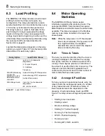
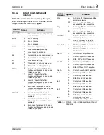
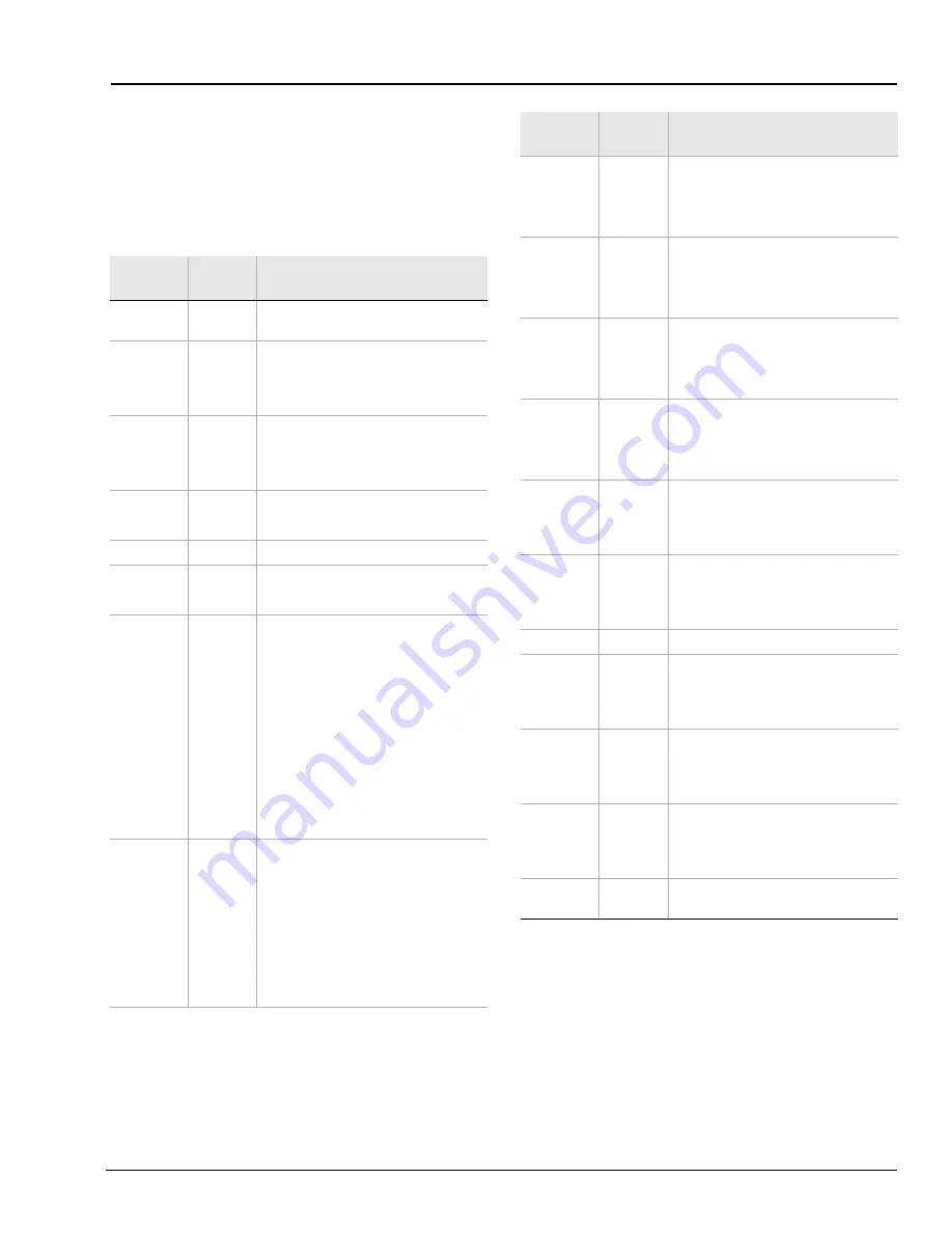
Table 9.5 summarizes the event report output,
input, and relay element control columns. Not all
relays include all the element types.
Table 9.5
Output, Input, and Element Event Report
Columns
Column
Heading
Symbol
Definition
All columns
•
Element/input/output not picked up
or not asserted.
Motor
S
Motor starting.
R
Motor running.
•
Motor stopped.
Load
J
Load Jam Trip picked up.
l
Load Loss Alarm picked up.
L
Load Loss Trip picked up.
46
A
Current Unbalance Alarm picked up.
T
Current Unbalance Trip picked up.
47
T
Phase Reversal Trip.
49
A
Thermal Element Alarm picked up.
T
Thermal Element Trip picked up.
50 O/C
Q
Negative-Sequence Definite-Time
Overcurrent Element picked up and
time delay expired.
1
Level 1 Phase Definite-Time
Overcurrent Element picked up and
time delay expired.
2
Level 2 Phase Definite-Time
Overcurrent Element picked up and
time delay expired.
b
Both Level 1 and Level 2 Phase
Overcurrent Elements picked up and
time delays expired.
50G O/C
1
Level 1 Residual Overcurrent
Element picked up and time delay
expired.
2
Level 2 Residual Overcurrent
Element picked up and time delay
expired.
b
Both Level 1 and Level 2 Residual
Overcurrent Elements picked up and
time delays expired.
Wdg
w
A Winding RTD has exceeded the
alarm temperature.
W
One or two Winding RTDs have
exceeded the trip temperature.
Brg
b
A Bearing RTD has exceeded the
alarm temperature.
B
One or two Bearing RTDs have
exceeded the trip temperature.
Oth RTD
o
An Other RTD has exceeded the
alarm temperature.
O
One or two Other RTDs have
exceeded the trip temperature.
Amb RTD
a
The Ambient RTD has exceeded the
alarm temperature.
A
The Ambient RTD has exceeded the
trip temperature.
Out T1
T
TRIP contact output asserted.
1
Contact output OUT1 asserted.
b
Both TRIP and OUT1 asserted.
Out 23
2
Contact output OUT2 asserted.
3
Contact output OUT3 asserted.
b
Both OUT2 and OUT3 asserted.
Out A
A
Contact output ALARM asserted.
In 12
1
Contact input IN1 asserted.
2
Contact input IN2 asserted.
b
Both IN1 and IN2 asserted.
In 34
3
Contact input IN3 asserted.
4
Contact input IN4 asserted.
b
Both IN3 and IN4 asserted.
In 56
5
Contact input IN5 asserted.
6
Contact input IN6 asserted.
b
Both IN5 and IN6 asserted.
In 7
7
Contact input IN7 (from
SIMPRO-100-RTD) asserted.
Column
Heading
Symbol
Definition
Summary of Contents for SIMPRO-100
Page 1: ...SIMPRO 100 Motor Protection Relay Instruction Manual Document No PRIM 2400C ...
Page 12: ...Contents SIMPRO 100 x PRIM 2400C ...
Page 16: ...Contents SIMPRO 100 xiv PRIM 2400C ...
Page 42: ...3 SIMPRO PC Software SIMPRO 100 40 PRIM 2400C ...
Page 100: ...6 ASCII Serial Port Operation SIMPRO 100 98 PRIM 2400C ...
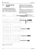
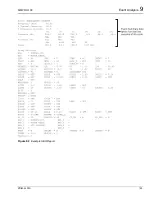
Page 127: ...SIMPRO 100 Event Analysis 9 PRIM 2400C 125 Figure 9 2 Example SER Report ...
Page 136: ...10 Maintenance Troubleshooting SIMPRO 100 134 PRIM 2400C ...
Page 138: ...A Firmware Versions SIMPRO 100 136 PRIM 2400C ...
Page 206: ...D SIMPRO PC Compatibility Features SIMPRO 100 204 PRIM 2400C ...
Page 214: ...E Motor Thermal Element SIMPRO 100 212 PRIM 2400C ...
Page 230: ...F SIMPRO 100 Relay Settings Sheets SIMPRO 100 228 PRIM 2400C ...
Page 239: ......


