


SIMPRO-100
Maintenance & Troubleshooting
10
PRIM-2400C
127
10 Maintenance & Troubleshooting
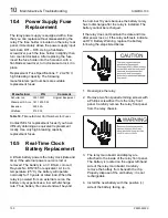
10.1
Routine Maintenance
Checks
Because the SIMPRO-100 Relay is equipped
with extensive self-tests, the most effective
maintenance task is to monitor the relay ALARM
contact. The ALARM output b-contact closes
when the relay is deenergized or when relay
self-tests fail. If you are monitoring the ALARM
contact, you know immediately if the relay is
deenergized or detects a failure. In addition, we
recommend review of relay event reports
following faults. This review frequently reveals
problems with equipment external to the relay
such as voltage transformers and control wiring.
The SIMPRO-100 Relay does not require specific
routine tests, but your operational standards may
require some periodic relay verification. If you
need or wish to perform periodic relay verification,
we recommend the following checks.
10.1.1
Relay Status Verification
Use the front-panel Status of Relay or serial port
STATUS command to verify that the relay
self-tests have not detected any out-of-tolerance
conditions.
10.1.2
Meter Verification
Verify that the relay is measuring current signals
and, if included, voltage signals by comparing the
relay meter reading to the reading of a separate
meter connected in series (for current circuits) or
parallel (for voltage circuits) with the relay input.
10.1.3
Contact Input Verification
With the relay and motor off-line, short-circuit the
individual relay contact inputs using a wire jumper
or the connected switch or contact. Using the
front-panel View Relay Word\Row 9 function,
check the contact input status in the relay
front-panel display. As you short-circuit each
input, its label (IN1, IN2, IN3, etc.) should appear
in the front-panel display.
10.1.4
Contact Output Verification
Use the front-panel Pulse Out Contact\Trip
command to close the TRIP output contact.
Repeat for the other output contacts. Make sure
that each contact operates properly in its
designated annunciation, control, or tripping
circuit. See Chapter 5, page 75 and
Section 6.8.23, page 92 for more details
regarding the PULSE command.
10.2
Self-Testing
The relay runs a variety of self-tests. As shown
below, when the relay detects certain types of
self-test failures, it closes the ALARM output
b-contact. Monitoring this contact is the single
most important relay maintenance activity that
you can perform.
The relay takes the following actions for
out-of-tolerance conditions in Table 10.1 on
page 128.
10.2.1
Protection Disabled
The relay:
•
Disables all protection functions and
stop/start logic
•
Deenergizes all output contacts
•
Extinguishes the Relay Enabled front-panel
LED
Summary of Contents for SIMPRO-100
Page 1: ...SIMPRO 100 Motor Protection Relay Instruction Manual Document No PRIM 2400C ...
Page 12: ...Contents SIMPRO 100 x PRIM 2400C ...
Page 16: ...Contents SIMPRO 100 xiv PRIM 2400C ...
Page 42: ...3 SIMPRO PC Software SIMPRO 100 40 PRIM 2400C ...
Page 100: ...6 ASCII Serial Port Operation SIMPRO 100 98 PRIM 2400C ...
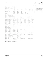
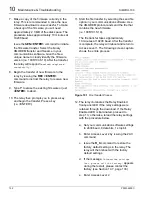
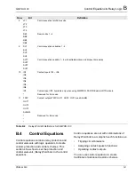
Page 127: ...SIMPRO 100 Event Analysis 9 PRIM 2400C 125 Figure 9 2 Example SER Report ...
Page 136: ...10 Maintenance Troubleshooting SIMPRO 100 134 PRIM 2400C ...
Page 138: ...A Firmware Versions SIMPRO 100 136 PRIM 2400C ...
Page 206: ...D SIMPRO PC Compatibility Features SIMPRO 100 204 PRIM 2400C ...
Page 214: ...E Motor Thermal Element SIMPRO 100 212 PRIM 2400C ...
Page 230: ...F SIMPRO 100 Relay Settings Sheets SIMPRO 100 228 PRIM 2400C ...
Page 239: ......


