


10
Maintenance & Troubleshooting
SIMPRO-100
128
PRIM-2400C
10.2.2
ALARM Output
The ALARM output contact signals an alarm
condition by going to its deenergized state.
•
The ALARM output b-contact closes for an
alarm condition; the ALARM output a-contact
opens for an alarm condition or if the relay is
deenergized.
•
The relay generates a STATUS report at the
serial port for failures.
•
The relay displays failure messages on the
relay VFD display.
Use the serial port STATUS command or
front-panel Status of Relay function to view the
relay self-test status.
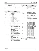
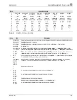
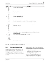
Table 10.1
Relay Self-tests
Self-Test
Description
Limits
Protection
Disabled on
Failure
ALARM
Output on
Failure
Front-Panel
Message on
Failure
DC Offset
Measures the dc offset at each of the input
channels.
160 mV
Yes
Latched
OFFSET
FAILURE
+5 V PS
Measures the +5 V power supply.
+4.65 V
+5.65 V
Yes
Latched
+5V FAILURE
-5 V PS
Measures the -5 V power supply.
-4.65 V
-5.40 V
Yes
Latched
-5V FAILURE
+15 V PS
Measures the +15 V power supply.
+14.00 V
+16.00 V
Yes
Latched
+15V
FAILURE
+28 V PS
Measures the +28 V power supply.
+24.00 V
Yes
Latched
+28V
FAILURE
TEMP
Measures the temperature at the A/D
voltage reference.
-50ºC
+100ºC
Yes
Latched
TEMPERATURE
FAILURE
RAM
Performs a read/write test on system RAM.
Yes
Latched
RAM FAILURE
ROM
Performs a checksum test on the relay
program memory.
Checksum
Yes
Latched
ROM FAILURE
CR_RAM
Performs a checksum test on the active
copy of the relay settings.
Checksum
Yes
Latched
CR_RAM
FAILURE
EEPROM
Performs a checksum test on the
nonvolatile copy of the relay settings.
Checksum
Yes
Latched
EEPROM
FAILURE
Micro-processor
Crystal
Monitors the microprocessor crystal.
Yes
Latched
CLOCK
STOPPED
Micro-processor The micro-processor examines each
program instruction, memory access, and
interrupt.
Test fails on
detection of an
invalid instruction,
memory access, or
spurious interrupt.
Yes
Latched
VECTOR nn
Clock Battery
Measures the real-time clock battery
voltage.
Battery Voltage
<2.50 V
No
Pulsed
Real-Time Clock Verifies the real-time clock chip
communication, time-keeping, and
memory functions.
No
Pulsed
Learned Cool
Time
Verifies the relay’s ability to learn the motor
cooling time.
Unable to write data
to target address
No
Pulsed
Learned Thermal
Capacity to Start
Verifies the relay’s ability to learn the motor
thermal capacity to start.
Unable to write data
to target address
No
Pulsed
Summary of Contents for SIMPRO-100
Page 1: ...SIMPRO 100 Motor Protection Relay Instruction Manual Document No PRIM 2400C ...
Page 12: ...Contents SIMPRO 100 x PRIM 2400C ...
Page 16: ...Contents SIMPRO 100 xiv PRIM 2400C ...
Page 42: ...3 SIMPRO PC Software SIMPRO 100 40 PRIM 2400C ...
Page 100: ...6 ASCII Serial Port Operation SIMPRO 100 98 PRIM 2400C ...
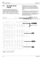
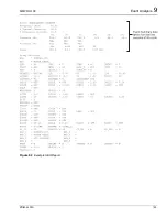
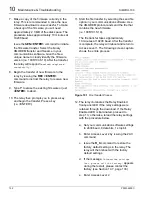
Page 127: ...SIMPRO 100 Event Analysis 9 PRIM 2400C 125 Figure 9 2 Example SER Report ...
Page 136: ...10 Maintenance Troubleshooting SIMPRO 100 134 PRIM 2400C ...
Page 138: ...A Firmware Versions SIMPRO 100 136 PRIM 2400C ...
Page 206: ...D SIMPRO PC Compatibility Features SIMPRO 100 204 PRIM 2400C ...
Page 214: ...E Motor Thermal Element SIMPRO 100 212 PRIM 2400C ...
Page 230: ...F SIMPRO 100 Relay Settings Sheets SIMPRO 100 228 PRIM 2400C ...
Page 239: ......


