


SIMPRO-100
Maintenance & Troubleshooting
10
PRIM-2400C
129
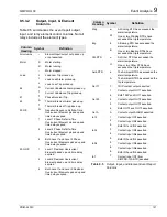
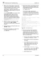
10.3
Troubleshooting
Procedure
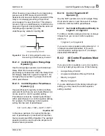
10.3.1
Relay Enabled Front-Panel
LED Dark
Table 10.2
Relay Enabled Front-panel LED Dark
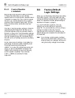
10.3.2
Cannot See Characters on
Relay Front-Panel Display
Screen
Table 10.3
Cannot See Characters on Relay
Front-Panel Display Screen
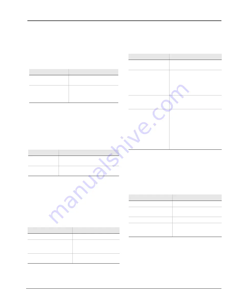
10.3.3
Relay Does Not Accurately
Measure Voltages or
Currents
Table 10.4
Relay Does Not Accurately Measure
Voltages or Currents
10.3.4
Relay Does Not Respond
to Commands From Device
Connected to Serial Port
Table 10.5
Relay Does Not Respond to Command
from Device Connected to Serial Port
10.3.5
Relay Does Not Respond
to Faults
Table 10.6
Relay Does Not Respond to Faults
Possible Cause
Solution
Input power not present
or fuse is blown.
Verify input power and fuse
continuity.
Self-test failure.
Check to see if the ALARM
b-contact is closed. Use the
front-panel Status of Relay
function to view self-test results.
Possible Cause
Solution
Relay front-panel
has timed-out
Press the
{ESC}
pushbutton to activate
display
Relay is
deenergized
Verify input power and fuse continuity
Possible Cause
Solution
Wiring error.
Verify input wiring.
Incorrect CTR, ITAP, CTRN,
INTAP, or PRT setting.
Verify signal source ratios,
connections, and associated
settings.
Voltage neutral terminal
(D09) not properly grounded.
Verify wiring and connections.
Possible Cause
Solution
Communications device
not connected to relay.
Verify cable connections.
Relay or communications
device at incorrect baud
rate or other
communication parameter
incompatibility, including
cabling error.
Verify terminal setup and cable
pinout.
Relay serial port has
received an XOFF, halting
communications.
Type
<CTRL> Q
to send relay on
XON and restart communications.
Rear-panel serial port
protocol set differently
than expected.
If you select Modbus
®
protocol,
the rear-panel EIA-232 serial port
is disabled. Use the EIA-485 port
to communicate with the relay
using Modbus, or use the
front-panel EIA-232 port to
communicate with the relay using
ASCII text. See Section 4.8,
page 70 for more information on
serial port configuration.
Possible Cause
Solution
Relay improperly set.
Verify relay settings.
Improper test source
settings.
Verify test source settings.
CT or PT input wiring error. Verify input wiring.
Failed relay self-test.
Use the front-panel Status of
Relay function to view self-test
results.
Summary of Contents for SIMPRO-100
Page 1: ...SIMPRO 100 Motor Protection Relay Instruction Manual Document No PRIM 2400C ...
Page 12: ...Contents SIMPRO 100 x PRIM 2400C ...
Page 16: ...Contents SIMPRO 100 xiv PRIM 2400C ...
Page 42: ...3 SIMPRO PC Software SIMPRO 100 40 PRIM 2400C ...
Page 100: ...6 ASCII Serial Port Operation SIMPRO 100 98 PRIM 2400C ...
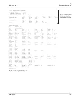
Page 127: ...SIMPRO 100 Event Analysis 9 PRIM 2400C 125 Figure 9 2 Example SER Report ...
Page 136: ...10 Maintenance Troubleshooting SIMPRO 100 134 PRIM 2400C ...
Page 138: ...A Firmware Versions SIMPRO 100 136 PRIM 2400C ...
Page 206: ...D SIMPRO PC Compatibility Features SIMPRO 100 204 PRIM 2400C ...
Page 214: ...E Motor Thermal Element SIMPRO 100 212 PRIM 2400C ...
Page 230: ...F SIMPRO 100 Relay Settings Sheets SIMPRO 100 228 PRIM 2400C ...
Page 239: ......


