


SIMPRO-100
Control Equations & Relay Logic
B
PRIM-2400C
147
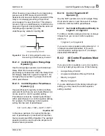
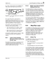
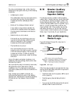
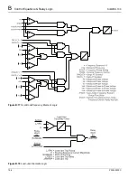
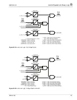
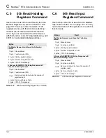
Four latch control switches in the SIMPRO-100
Relay provide latching relay type functions.
Figure B.6
Latch Control Switches Drive Latch Bits
LT1 – LT4
The output of the latch control switch in
Figure B.6 is a Relay Word bit LTn (n = 1 – 4),
called a latch bit. The latch control switch logic in
Figure B.6 repeats for each latch bit LT1 – LT4.
Use these latch bits in control equations.
These latch control switches each have the
following control equation settings:
•
SETn sets latch bit LTn to logical 1 when
SETn control equation result is logical 1.
•
RSTn reset latch bit LTn to logical 0 when
RSTn control equation result is logical 1.
If both SETn and RSTn assert to logical 1, RSTn
has priority and latch bit LTn deasserts to
logical 0.
B.8.1
Latch Control Switch
States Are Retained During
Power Loss
The states of the latch bits are retained if power
to the relay is lost and then restored. This
capability makes the latch bit feature behave the
same as traditional latching relays.
B.8.2
Make Latch Control Switch
Settings With Care
The latch bit states are stored in nonvolatile
memory so they can be retained during power
loss. The nonvolatile memory is rated for a finite
number of writes for all cumulative latch bit state
changes. Exceeding the limit can result in an
EEPROM self-test failure. An average of 150
cumulative latch bit state changes per day can be
made for a 25-year relay service life.
The control equation settings SETn and RSTn for
any given latch bit LTn (n = 1 – 4; see Figure B.6)
must be set with care. Settings SETn and RSTn
must not result in continuous cyclical operation of
latch bit LTn. Use timers to qualify conditions set
in settings SETn and RSTn.
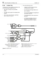
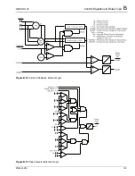
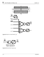
B.9
Stop/Trip Logic
The SIMPRO-100 Relay tripping logic is designed
to trip or stop motors energized through circuit
breakers or contactors. The relay logic lets you
define the conditions that cause a trip, the
conditions that unlatch the trip, and the
performance of the relay output contact motor
contactor or breaker. Figure B.7, page 148
illustrates the tripping logic.
B.9.1
Initiate Trip
The SIMPRO-100 Relay Trip Logic offers three
ways to stop the protected motor:
•
TRIP control equation
•
Front panel, Modbus
®
, or serial port STOP
command
•
Trips generated by the remote bit function
Any of the three of these conditions will trigger an
event report. The relay controls the TRIP output
contacts depending on the Enable Trip Contact
Fail-Safe setting. Refer to Figure B.7, page 148.
Set the TRIP control equation to include an
OR-combination of all the enabled protection
element Relay Word bits that you want to cause
the relay to trip. Use the factory default setting as
a guideline.
Summary of Contents for SIMPRO-100
Page 1: ...SIMPRO 100 Motor Protection Relay Instruction Manual Document No PRIM 2400C ...
Page 12: ...Contents SIMPRO 100 x PRIM 2400C ...
Page 16: ...Contents SIMPRO 100 xiv PRIM 2400C ...
Page 42: ...3 SIMPRO PC Software SIMPRO 100 40 PRIM 2400C ...
Page 100: ...6 ASCII Serial Port Operation SIMPRO 100 98 PRIM 2400C ...
Page 127: ...SIMPRO 100 Event Analysis 9 PRIM 2400C 125 Figure 9 2 Example SER Report ...
Page 136: ...10 Maintenance Troubleshooting SIMPRO 100 134 PRIM 2400C ...
Page 138: ...A Firmware Versions SIMPRO 100 136 PRIM 2400C ...
Page 206: ...D SIMPRO PC Compatibility Features SIMPRO 100 204 PRIM 2400C ...
Page 214: ...E Motor Thermal Element SIMPRO 100 212 PRIM 2400C ...
Page 230: ...F SIMPRO 100 Relay Settings Sheets SIMPRO 100 228 PRIM 2400C ...
Page 239: ......


