


SIMPRO-100
Control Equations & Relay Logic
B
PRIM-2400C
151
B.13
Speed Switch
Control Equation
Setting
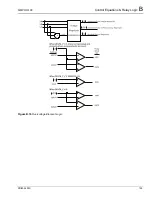
The speed switch control equation, SPEEDSW,
defines the relay input contact that is connected
to the motor speed switch. The factory default
setting allows you to connect the speed switch
contact to input IN3 at the relay or input IN7 at the
external RTD module, if installed. The Speed
Switch Trip logic, (Section 4.4.8, page 58), uses
the result of the SPEEDSW control equation.
B.14
Event Triggering
Control Equation
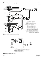
The event report trigger control equation, ER,
triggers standard event reports for conditions
other than trip conditions. When setting ER sees
a logical 0 to logical 1 transition, it generates an
event report (if the relay is not already generating
a report that encompasses the new transition).
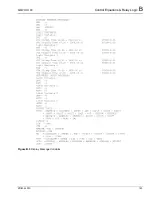
The factory setting shown in Table B.3 on
page 142 includes a rising-edge operator [/] in
front of each of the alarm elements. This is used
to trigger an event report at alarm inception.
Falling-edge operators are used to generate an
event report at frequency element dropout, when
the system frequency has stabilized at or near the
nominal frequency.
B.15
Contact Output
Control
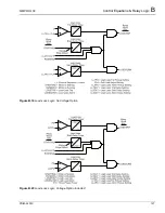
Control equation settings and their respective
fail-safe settings directly control the contact
outputs OUT1, OUT2, and OUT3. The control
equation settings let you program individual
contact outputs using single Relay Word bits for
element testing purposes or to create more
complex functions by combining Relay Word bits
and control equation operators.
B.16
Remote Control
Switches
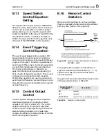
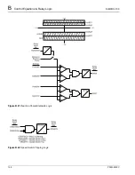
Remote control switches do not have settings;
they are operated via the serial communications
port only (see Section 6.8.4, page 90).
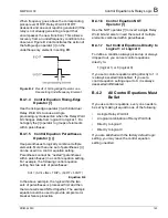
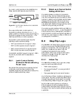
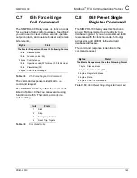
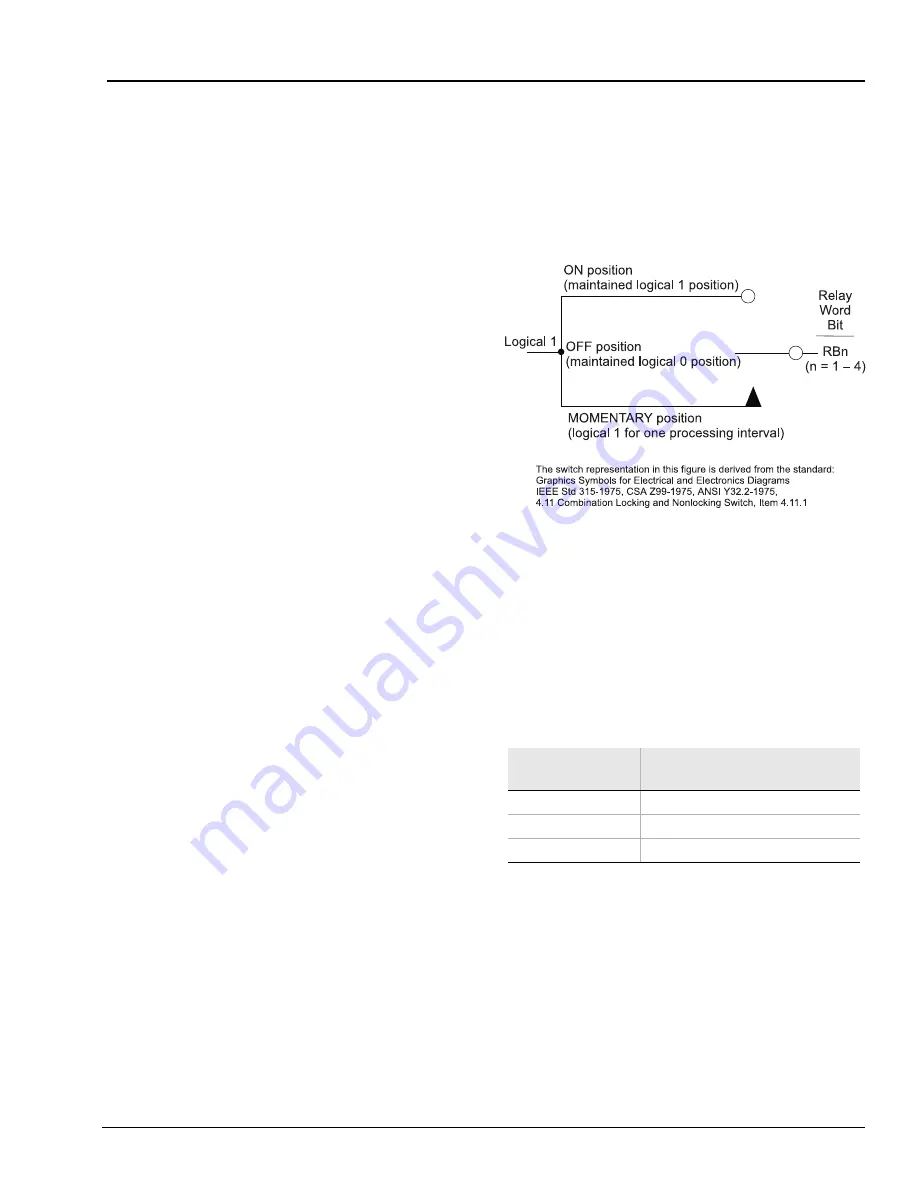
Figure B.9
Remote Control Switches Drive Remote
Bits RB1 – RB4
The outputs of the remote control switches in
Figure B.9 are Relay Word bits RBn (n = 1 – 4),
called remote bits. Use these remote bits in
control equations.
Any given remote control switch can be put in one
of three positions shown in Table B.4.
Table B.4
Remote Control Switch
Control Switch
Position
Description
ON
logical 1
OFF
logical 0
MOMENTARY
logical 1 for one processing interval
Summary of Contents for SIMPRO-100
Page 1: ...SIMPRO 100 Motor Protection Relay Instruction Manual Document No PRIM 2400C ...
Page 12: ...Contents SIMPRO 100 x PRIM 2400C ...
Page 16: ...Contents SIMPRO 100 xiv PRIM 2400C ...
Page 42: ...3 SIMPRO PC Software SIMPRO 100 40 PRIM 2400C ...
Page 100: ...6 ASCII Serial Port Operation SIMPRO 100 98 PRIM 2400C ...
Page 127: ...SIMPRO 100 Event Analysis 9 PRIM 2400C 125 Figure 9 2 Example SER Report ...
Page 136: ...10 Maintenance Troubleshooting SIMPRO 100 134 PRIM 2400C ...
Page 138: ...A Firmware Versions SIMPRO 100 136 PRIM 2400C ...
Page 206: ...D SIMPRO PC Compatibility Features SIMPRO 100 204 PRIM 2400C ...
Page 214: ...E Motor Thermal Element SIMPRO 100 212 PRIM 2400C ...
Page 230: ...F SIMPRO 100 Relay Settings Sheets SIMPRO 100 228 PRIM 2400C ...
Page 239: ......


