


E
Motor Thermal Element
SIMPRO-100
206
PRIM-2400C
The purpose of motor thermal protection is to
allow the motor to start and run within the
manufacturer’s published guidelines, but trip if
the motor heat energy exceeds those ratings due
to overloads, negative-sequence current, or
locked rotor starting.
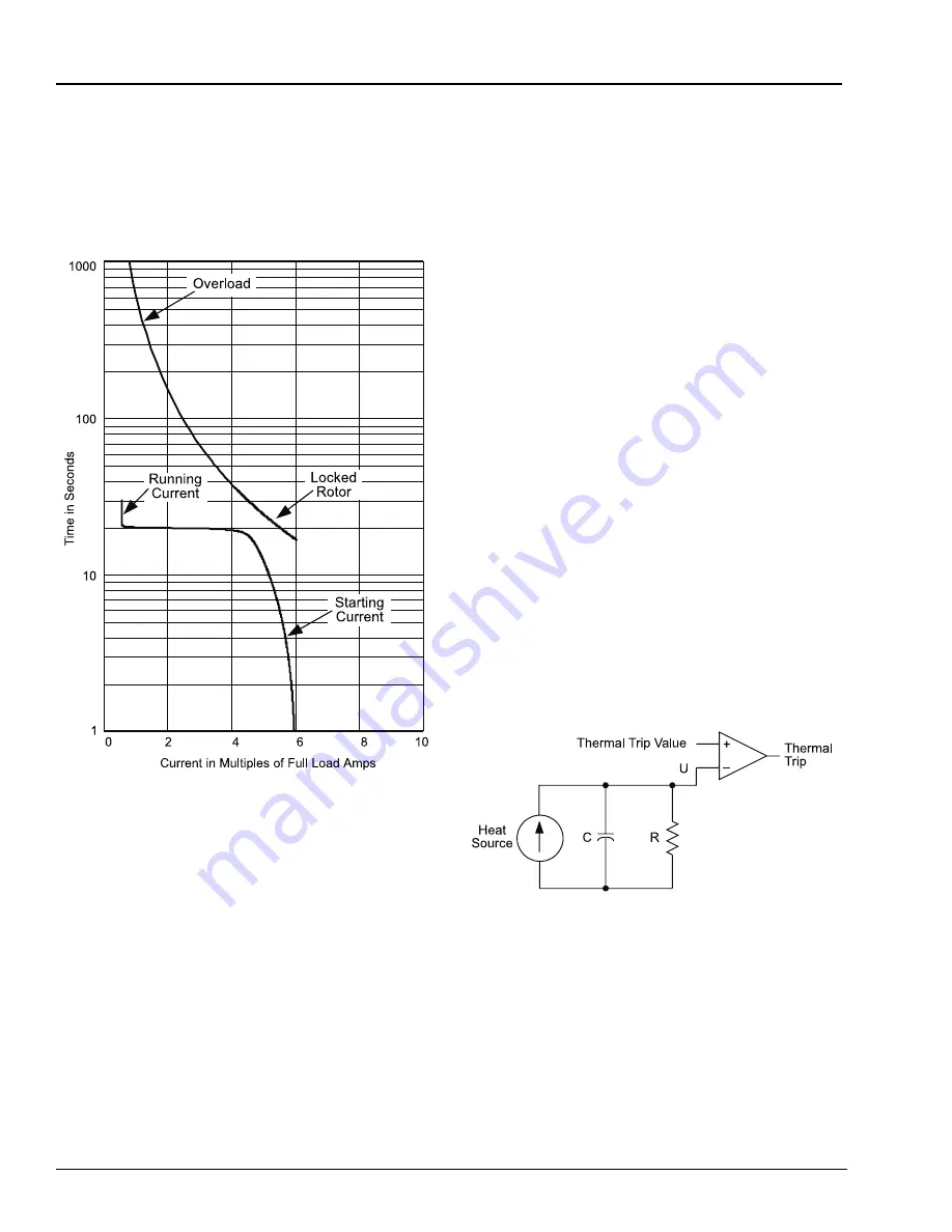
Figure E.1
Motor Thermal Limit Characteristic
Plotted With Motor Starting Current
Figure E.1 shows a typical motor thermal limit
characteristic plotted with the motor starting
current. Some motor protection applications use
an inverse-time phase overcurrent element to
provide locked rotor and overload protection
along with a separate negative-sequence
overcurrent relay to prevent overheating due to
current unbalance. Unfortunately, neither of these
elements accounts for the motor thermal history
or track temperature excursions. The
SIMPRO-100 Relay thermal element, with its
integrated design, offers distinct advantages over
the use of discrete elements.
The SIMPRO-100 Relay thermal element always
operates in one of two modes: starting or running.
In starting mode, the thermal element provides
locked rotor protection, allowing the motor to
absorb the high energy of the I
2
t threshold
represented by the rated locked rotor current and
time. In running mode, the thermal element
provides overload and unbalance protection by
limiting the motor heat energy estimate to a value
represented by the service factor and two other
motor parameters.
E.3
The Basic Thermal
Element
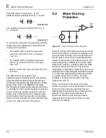
Figure E.2 shows a simple electrical analog for a
thermal system. The thermal element includes:
•
A heat source, modeled as a current source
•
A thermal capacitance, modeled as a
capacitor
•
A thermal impedance to ambient, modeled as
a resistor
•
A comparator, to compare the present heat
estimate U, to the Thermal Trip Value
Figure E.2
Electrical Analog of a Thermal System
In order to define a thermal element for an
induction motor, the characteristics of each
component in Figure E.2 must be defined,
starting with the heat source. In an induction
motor, heat principally is caused by I
2
r losses. To
consider the effects of negative-sequence current
on the motor, it is called out separately in
Equation E.1.
Summary of Contents for SIMPRO-100
Page 1: ...SIMPRO 100 Motor Protection Relay Instruction Manual Document No PRIM 2400C ...
Page 12: ...Contents SIMPRO 100 x PRIM 2400C ...
Page 16: ...Contents SIMPRO 100 xiv PRIM 2400C ...
Page 42: ...3 SIMPRO PC Software SIMPRO 100 40 PRIM 2400C ...
Page 100: ...6 ASCII Serial Port Operation SIMPRO 100 98 PRIM 2400C ...
Page 127: ...SIMPRO 100 Event Analysis 9 PRIM 2400C 125 Figure 9 2 Example SER Report ...
Page 136: ...10 Maintenance Troubleshooting SIMPRO 100 134 PRIM 2400C ...
Page 138: ...A Firmware Versions SIMPRO 100 136 PRIM 2400C ...
Page 206: ...D SIMPRO PC Compatibility Features SIMPRO 100 204 PRIM 2400C ...
Page 214: ...E Motor Thermal Element SIMPRO 100 212 PRIM 2400C ...
Page 230: ...F SIMPRO 100 Relay Settings Sheets SIMPRO 100 228 PRIM 2400C ...
Page 239: ......


