


E
Motor Thermal Element
SIMPRO-100
208
PRIM-2400C
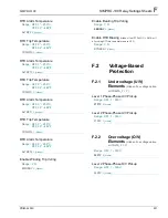
When the motor is running (S
≈
0), the
positive-sequence heating factor K
1
, is found.
Equation E.6
The negative-sequence heating factor, K
2
, at
S
≈
0 is found.
Equation E.7
To summarize, based on the assumption that the
locked-rotor rotor resistance is three times the
running rotor resistance:
•
The heating factor of positive-sequence
current K
1
, when the motor is running is
1 per unit
•
The heating factor of negative-sequence
current, K
2
, when the motor is running is
5 per unit
•
Both K
1
and K
2
are 3 per unit when the rotor
is locked
The differences in the positive- and
negative-sequence heating factors immediately
suggest that the thermal element should have
two states representing the starting and running
states of the motor. The SIMPRO-100 Relay
thermal element automatically selects which state
to use based on the measured positive-sequence
current. When the positive-sequence current is
greater than 2.5 times the motor rated full load
current setting, the relay uses the starting state.
When current is less than 2.5 times rated full load
current, the relay uses the running state.
E.4
Motor Starting
Protection
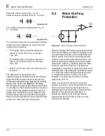
Figure E.4
Motor Starting Thermal Element
Figure E.4 shows the thermal element used when
the motor is starting. Locked rotor heating occurs
over just a few seconds, so the model assumes
that no heat is lost to the surroundings and the
resistor is removed from the thermal circuit. The
thermal trip value is defined by the motor rated
locked rotor current I
L
, squared, times the rated
hot motor locked rotor time To. The thermal
capacitance is selected to match the heat source
heating factor 3. By setting the capacitance equal
to 3, when the motor positive-sequence current
I
1
, equals locked rotor current I
L
, the heat
estimate U, reaches the trip value in exactly
locked rotor time To.
When a successful motor start occurs and
positive-sequence current drops below 2.5 times
full load current, the relay switches from the
starting thermal element to the running thermal
element. The present heat estimate U, is
transferred directly to the running element,
representing the heat build-up that occurred
during motor starting.
Summary of Contents for SIMPRO-100
Page 1: ...SIMPRO 100 Motor Protection Relay Instruction Manual Document No PRIM 2400C ...
Page 12: ...Contents SIMPRO 100 x PRIM 2400C ...
Page 16: ...Contents SIMPRO 100 xiv PRIM 2400C ...
Page 42: ...3 SIMPRO PC Software SIMPRO 100 40 PRIM 2400C ...
Page 100: ...6 ASCII Serial Port Operation SIMPRO 100 98 PRIM 2400C ...
Page 127: ...SIMPRO 100 Event Analysis 9 PRIM 2400C 125 Figure 9 2 Example SER Report ...
Page 136: ...10 Maintenance Troubleshooting SIMPRO 100 134 PRIM 2400C ...
Page 138: ...A Firmware Versions SIMPRO 100 136 PRIM 2400C ...
Page 206: ...D SIMPRO PC Compatibility Features SIMPRO 100 204 PRIM 2400C ...
Page 214: ...E Motor Thermal Element SIMPRO 100 212 PRIM 2400C ...
Page 230: ...F SIMPRO 100 Relay Settings Sheets SIMPRO 100 228 PRIM 2400C ...
Page 239: ......


