


SIMPRO-100
Installation
2
PRIM-2400C
27
2 Installation
2.1
Panel Cut & Drill
Plans
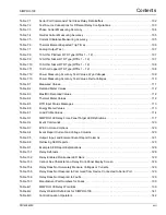
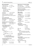
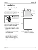
Figure 2.1, page 27 shows the mechanical
dimensions of the SIMPRO-100 Relay.
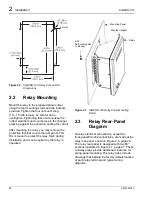
Figure 2.2, page 28 shows the dimensions of the
panel cutout required to mount the relay.
Guard against accidental contact with relay rear
terminals by mounting the relay in an approved
enclosure or by using any of the following
methods:
•
Locate the relay in a room, vault, or similar
enclosure that is accessible only to qualified
persons.
•
Locate the relay on a suitable balcony, gallery,
or platform that is elevated and accessible
only to qualified persons.
•
Use suitable permanent, substantial partitions
or screens arranged so that only qualified
persons have access to the space within
reach of live parts. Locate and size any
openings in partitions or screens so that
neither people nor conducting objects are
likely to come into accidental contact with live
parts.
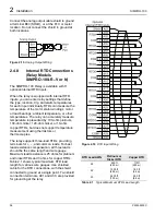
Figure 2.1
SIMPRO-100 Relay Mechanical
Dimensions (Front and Top Views)
Summary of Contents for SIMPRO-100
Page 1: ...SIMPRO 100 Motor Protection Relay Instruction Manual Document No PRIM 2400C ...
Page 12: ...Contents SIMPRO 100 x PRIM 2400C ...
Page 16: ...Contents SIMPRO 100 xiv PRIM 2400C ...
Page 42: ...3 SIMPRO PC Software SIMPRO 100 40 PRIM 2400C ...
Page 100: ...6 ASCII Serial Port Operation SIMPRO 100 98 PRIM 2400C ...
Page 127: ...SIMPRO 100 Event Analysis 9 PRIM 2400C 125 Figure 9 2 Example SER Report ...
Page 136: ...10 Maintenance Troubleshooting SIMPRO 100 134 PRIM 2400C ...
Page 138: ...A Firmware Versions SIMPRO 100 136 PRIM 2400C ...
Page 206: ...D SIMPRO PC Compatibility Features SIMPRO 100 204 PRIM 2400C ...
Page 214: ...E Motor Thermal Element SIMPRO 100 212 PRIM 2400C ...
Page 230: ...F SIMPRO 100 Relay Settings Sheets SIMPRO 100 228 PRIM 2400C ...
Page 239: ......


