


SIMPRO-100
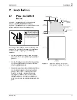
Installation
2
PRIM-2400C
31
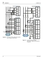
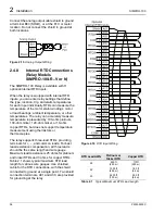
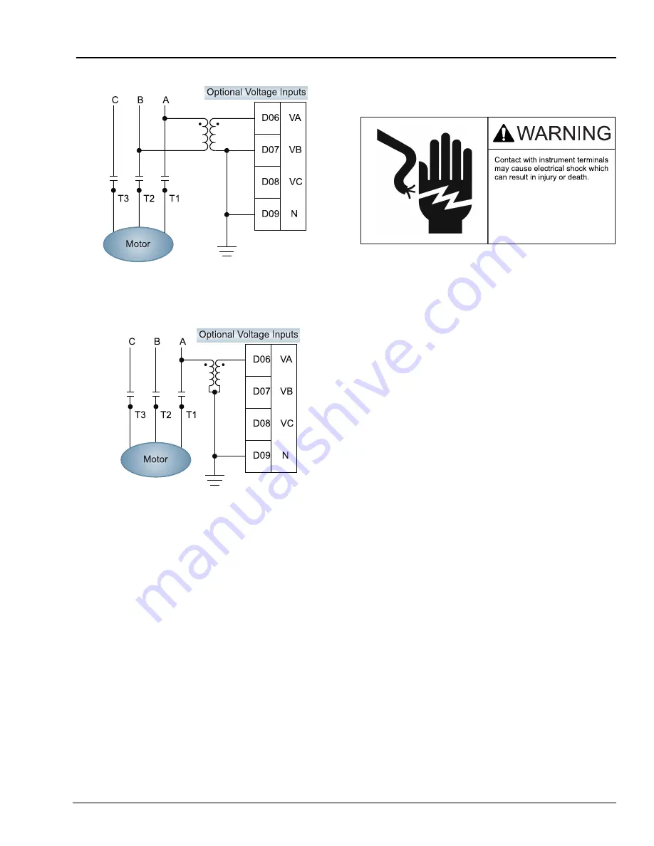
Figure 2.8
Example AC Voltage Wiring Diagram,
Single Phase-to-Phase Voltage
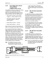
Figure 2.9
Example AC Voltage Wiring Diagram,
Single Phase-to-Neutral Voltage
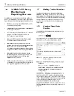
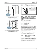
2.4
Relay Connections
2.4.1
Input Power Connections
The SIMPRO-100 Relay power supply has a
broad operating range that can accept ac or dc
inputs.
Power Supply Operating Range:
•
95 – 240 ± 10% Vac 50/60 Hz
•
20 – 250 ± 20% Vdc
•
< 15 VA, typical
The relay power supply is fused internally. If the
fuse operates, make sure that the cause of the
fuse operation has been isolated and corrected
before replacing the fuse and returning the relay
to service. See Section 10: Maintenance &
Troubleshooting for instructions on how to
replace the power supply fuse.
Replacement Power Supply Fuse Ratings:
•
T 2 A/250 V, high breaking capacity
2.4.2
Relay Chassis Ground
Connection
Terminals D01 and D10 are the chassis ground
terminals. At least one of these terminals must be
solidly connected to the cabinet ground bus for
correct relay operation and personal safety.
Summary of Contents for SIMPRO-100
Page 1: ...SIMPRO 100 Motor Protection Relay Instruction Manual Document No PRIM 2400C ...
Page 12: ...Contents SIMPRO 100 x PRIM 2400C ...
Page 16: ...Contents SIMPRO 100 xiv PRIM 2400C ...
Page 42: ...3 SIMPRO PC Software SIMPRO 100 40 PRIM 2400C ...
Page 100: ...6 ASCII Serial Port Operation SIMPRO 100 98 PRIM 2400C ...
Page 127: ...SIMPRO 100 Event Analysis 9 PRIM 2400C 125 Figure 9 2 Example SER Report ...
Page 136: ...10 Maintenance Troubleshooting SIMPRO 100 134 PRIM 2400C ...
Page 138: ...A Firmware Versions SIMPRO 100 136 PRIM 2400C ...
Page 206: ...D SIMPRO PC Compatibility Features SIMPRO 100 204 PRIM 2400C ...
Page 214: ...E Motor Thermal Element SIMPRO 100 212 PRIM 2400C ...
Page 230: ...F SIMPRO 100 Relay Settings Sheets SIMPRO 100 228 PRIM 2400C ...
Page 239: ......


