


2
Installation
SIMPRO-100
36
PRIM-2400C
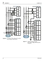
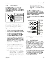
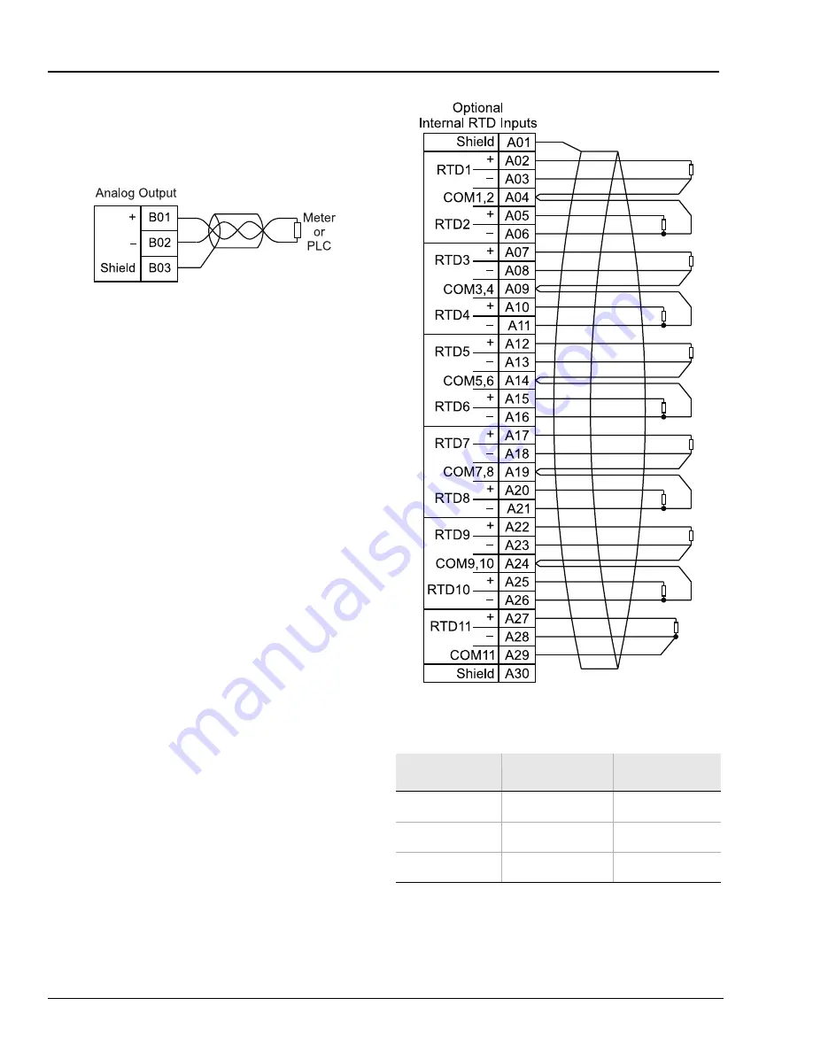
Connect the analog output cable shield to ground
at terminal B03 (SHLD), or at the PLC or meter
location. Do not connect the shield to ground at
both locations.
Figure 2.15
Analog Output Wiring
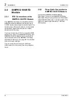
2.4.8
Internal RTD Connections
(Relay Models
SIMPRO-100–R–V or N)
The SIMPRO-100 Relay is available with 11
optional internal RTD inputs.
When the relay is equipped with internal RTD
inputs, you can enter relay settings that define
the type, location, trip, and alarm temperatures
for each input individually. RTDs can measure the
temperature of the motor stator windings, motor
or load bearings, ambient temperature, or other
temperatures. The relay can accurately measure
temperature represented by 100-ohm platinum,
100-ohm nickel, 120-ohm nickel, or 10-ohm
copper RTDs, but does not support temperature
measurement using thermistors or
thermocouples.
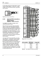
The relay supports three-lead RTDs, providing
terminals for +, –, and common leads. For best
lead-resistance compensation, all three leads
should be the same length and wire gauge.
Maximum lead resistance is 25 ohms for platinum
and nickel RTDs and 3 ohms for copper RTDs.
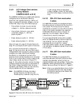
Table 2.1 shows typical maximum RTD lead
length for various wire gauges. Use shielded
cable for the RTD connections, with the shield
connected to ground at a single point. Two shield
connection terminals, A01 and A30, are provided
for grounding at the relay.
Figure 2.16
RTD Input Wiring
Table 2.1
Typical Maximum RTD Lead Length
RTD Lead AWG
Platinum or
Nickel RTD
Copper RTD
24
950 ft
(290 m)
110ft
(290 m)
22
1500 ft
(455 m)
180 ft
(54 m)
20
2400 ft
(730 m)
290 ft
(88 m)
Summary of Contents for SIMPRO-100
Page 1: ...SIMPRO 100 Motor Protection Relay Instruction Manual Document No PRIM 2400C ...
Page 12: ...Contents SIMPRO 100 x PRIM 2400C ...
Page 16: ...Contents SIMPRO 100 xiv PRIM 2400C ...
Page 42: ...3 SIMPRO PC Software SIMPRO 100 40 PRIM 2400C ...
Page 100: ...6 ASCII Serial Port Operation SIMPRO 100 98 PRIM 2400C ...
Page 127: ...SIMPRO 100 Event Analysis 9 PRIM 2400C 125 Figure 9 2 Example SER Report ...
Page 136: ...10 Maintenance Troubleshooting SIMPRO 100 134 PRIM 2400C ...
Page 138: ...A Firmware Versions SIMPRO 100 136 PRIM 2400C ...
Page 206: ...D SIMPRO PC Compatibility Features SIMPRO 100 204 PRIM 2400C ...
Page 214: ...E Motor Thermal Element SIMPRO 100 212 PRIM 2400C ...
Page 230: ...F SIMPRO 100 Relay Settings Sheets SIMPRO 100 228 PRIM 2400C ...
Page 239: ......


