


SIMPRO-100
Installation
2
PRIM-2400C
37
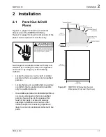
2.4.9
AC Voltage Connections
(Relay Models
SIMPRO-100-R or N-V)
The SIMPRO-100 Relay is available with optional
voltage inputs and associated metering,
protection, and reporting functions. When your
relay is equipped to measure voltages, you can
connect the relay in any of the following ways:
•
Three-phase, four-wire, wye-connected
voltages, 0 – 300 Vac, phase-to-neutral.
•
Three-phase, three-wire, open-delta
connected voltages, 0 – 300 Vac,
phase-to-phase.
•
Single phase-to-neutral, 0 – 300 Vac.
•
Single phase-to-phase, 0 – 300 Vac.
Refer to Figure 2.6, page 30 through Figure 2.9,
page 31 for examples of each type of connection.
The connection method shown in Figure 2.8,
page 31 may allow you to use the motor control
voltage transformer to supply the phase-to-phase
voltage for the relay. If the control voltage
transformer is connected to the bus for the
protected motor and the transformer is connected
A-B, you can connect the ac control voltage to the
relay voltage inputs, as shown in Figure 2.8,
page 31. Using this connection method, the relay
voltage measurement accuracy is dependent on
the control voltage transformer ratio accuracy,
regulation, and loading. However, this accuracy
may be satisfactory for your application.
Note:
The SIMPRO-100 Relay calculates
system frequency for the over- and
underfrequency elements using the A-N
or A-B voltage. When single-phase
voltage is applied, make sure that either
the A-N or A-B voltage is connected to the
relay.
2.4.10
EIA-232 Communication
Cables
The SIMPRO-100 Relay is equipped with 9-pin
EIA-232 serial port connectors on the front and
rear panels. The front-panel port is always
available for connection to a local PC for setting
entry or information download. Use Siemens
Cable SIM-232 (pinout shown in Figure 6.1,
page 86) or a null-modem cable for direct
connection to a local PC serial port.
The rear-panel EIA-232 serial port is available
when you disable Modbus‚ protocol support by
relay settings. You can connect the relay
rear-panel port to a local PC or modem.
Fiber-optic cable modems are also available for
communication at distances greater than 50 feet
(15.2 meters).
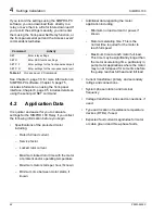
2.4.11
EIA-485 Communication
Cables
The SIMPRO-100 Relay is equipped with a
rear-panel EIA-485 serial port connector which
operates using Modbus protocol when you
enable that feature by relay settings. Connect the
SIMPRO-100 Relay EIA-485 port to a Modbus
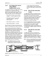
Master device as shown in Figure 2.17, page 37.
Note:
When you enable Modbus protocol for the
rear-panel serial port, the relay disables
the EIA-232 serial port and enables the
EIA-485 serial port.
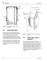
Figure 2.17
Rear-Panel EIA-485 Serial Port Connections
Summary of Contents for SIMPRO-100
Page 1: ...SIMPRO 100 Motor Protection Relay Instruction Manual Document No PRIM 2400C ...
Page 12: ...Contents SIMPRO 100 x PRIM 2400C ...
Page 16: ...Contents SIMPRO 100 xiv PRIM 2400C ...
Page 42: ...3 SIMPRO PC Software SIMPRO 100 40 PRIM 2400C ...
Page 100: ...6 ASCII Serial Port Operation SIMPRO 100 98 PRIM 2400C ...
Page 127: ...SIMPRO 100 Event Analysis 9 PRIM 2400C 125 Figure 9 2 Example SER Report ...
Page 136: ...10 Maintenance Troubleshooting SIMPRO 100 134 PRIM 2400C ...
Page 138: ...A Firmware Versions SIMPRO 100 136 PRIM 2400C ...
Page 206: ...D SIMPRO PC Compatibility Features SIMPRO 100 204 PRIM 2400C ...
Page 214: ...E Motor Thermal Element SIMPRO 100 212 PRIM 2400C ...
Page 230: ...F SIMPRO 100 Relay Settings Sheets SIMPRO 100 228 PRIM 2400C ...
Page 239: ......


