


4
Settings Calculation
SIMPRO-100
46
PRIM-2400C
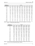
Example:
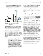
Thermal Element Rating Method
Setting
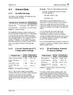
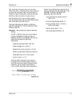
A 4160 V, 600 HP motor is to be protected
using the SIMPRO-100 Relay Thermal
Element Rating Method. The motor data
sheet includes the following information.
Rated Horsepower (HP) = 600 HP
Rated Voltage (V) = 4160 V
Rated Full Load Current (A) = 62.1 A
Rated Locked Rotor Amps (A) = 382.5 A
Safe Stall Time at 100% Volts
Cold = 21 seconds
Hot = 16 seconds
Service Factor = 1.2
Phase current transformers having 80:5
ratios are selected for the application. The
SIMPRO-100 Relay settings for the
application are calculated as shown below.
Current Transformer Ratio (CTR) =
80/5 = 16
CT Secondary Rating (ITAP) = 5
Full Load Amps (FLA) = 62.1/16 =
3.88 A secondary
Service Factory (SF) = 1.2
Locked Rotor Amps (LRA) = 382.5/16 =
23.9 A secondary
Hot Locked Rotor Time (LRTHOT) =
16 seconds
Cold Locked Rotor Time (LRTCOLD) =
21 seconds
The Locked Rotor Trip Time Dial setting reduces
or extends the allowed accelerating time under
locked rotor conditions. You can always safely set
this value equal to 1.00. If you know that the
driven load will always accelerate in less than the
rated locked rotor time, you may wish to use a
Locked Rotor Trip Time Dial less than 1.00 to
provide a faster trip in locked rotor conditions. Do
not set the Locked Rotor Trip Time Dial setting
greater than 1.00, except in an emergency to
allow a start with a longer than normal
accelerating time.
Example:
Locked Rotor Trip Time Dial
Setting Calculation
In a particular application, a motor with a
10 second hot locked rotor time always
starts in 5 seconds.
Setting the Locked Rotor Trip Time Dial
setting equal to 0.75 causes the relay to trip
in 7.5 seconds under locked rotor
conditions. This setting allows ample time
for the motor to start, but does not subject
the motor to the full 10 seconds of locked
rotor current if a locked rotor start attempt
takes place.
Continue calculating the balance of thermal
element settings with Section 4.4.1.4, page 53.
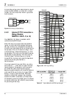
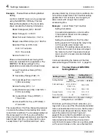
4.4.1.2
Thermal Element GENERIC
Setting Method
Table 4.7
Thermal Element Configuration Settings,
Setting Method = GENERIC
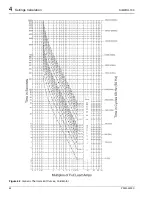
For simple, yet thorough motor protection, you
may elect to use one of the 45 available standard
motor overload/locked rotor curves. Set the motor
rated Full Load Amps and Service Factor, then
select the desired curve from Figure 4.2,
page 48. Be sure that the standard curve you
select trips in a time less than or equal to the
motor rated locked rotor time at locked rotor
current. Each increase in the curve number yields
a 2.5 second increase in the curve thermal limit
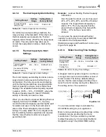
Setting Prompt
Setting
Range
Setting Name =
Example Setting
Setting Method
Rating,
Generic, User SETMETH = GENERIC
Full Load Amps
2.50 – 8.00 A
ITAP = 5 A
FLA = 5.00
0.50 – 1.60 A
FLA = 1.00
Service Factor
1.00 – 1.50
SF = 1.15
Curve Number
1 – 45
CURVE = 1
Summary of Contents for SIMPRO-100
Page 1: ...SIMPRO 100 Motor Protection Relay Instruction Manual Document No PRIM 2400C ...
Page 12: ...Contents SIMPRO 100 x PRIM 2400C ...
Page 16: ...Contents SIMPRO 100 xiv PRIM 2400C ...
Page 42: ...3 SIMPRO PC Software SIMPRO 100 40 PRIM 2400C ...
Page 100: ...6 ASCII Serial Port Operation SIMPRO 100 98 PRIM 2400C ...
Page 127: ...SIMPRO 100 Event Analysis 9 PRIM 2400C 125 Figure 9 2 Example SER Report ...
Page 136: ...10 Maintenance Troubleshooting SIMPRO 100 134 PRIM 2400C ...
Page 138: ...A Firmware Versions SIMPRO 100 136 PRIM 2400C ...
Page 206: ...D SIMPRO PC Compatibility Features SIMPRO 100 204 PRIM 2400C ...
Page 214: ...E Motor Thermal Element SIMPRO 100 212 PRIM 2400C ...
Page 230: ...F SIMPRO 100 Relay Settings Sheets SIMPRO 100 228 PRIM 2400C ...
Page 239: ......


