


SIMPRO-100
Settings Calculation
4
PRIM-2400C
53
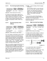
4.4.1.4
Thermal Capacity Alarm Setting
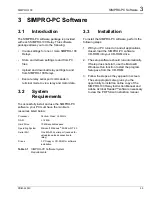
Table 4.12
Thermal Capacity Alarm Setting
For all thermal element settings methods, the
relay provides a thermal alarm. When the motor
thermal capacity used exceeds the Thermal
Capacity Alarm Pickup (TCAPU), the relay issues
an alarm. The early alarm may allow you to
correct the load problem before a thermal trip
occurs.
4.4.1.5
Thermal Capacity to Start
Settings
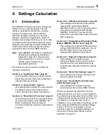
Table 4.13
Thermal Capacity to Start Settings
The motor tripping and starting functions include
supervision to help prevent a thermal trip on a
normal start. The relay prevents motor starting
until the thermal element has enough available
thermal capacity to allow a motor start without
tripping. The available thermal capacity required
to start is (100% – 10% – TCSTART), where the
Thermal Capacity Used To Start (TCSTART)
setting or the relay can learn a value.
When you use the Use Learned Starting Thermal
Capacity function (TCLRNEN = Y), the relay
records the thermal capacity used during the past
five starts and uses it in the thermal model in
place of the Thermal Capacity Used to Start
setting. The relay adds 10% to the largest of the
last five starting thermal capacities and requires
that the motor thermal model cool enough to
permit that start.
Example:
Learned Starting Thermal Capacity
Calculation
Over the past five starts, a motor has used
24%, 27%, 22%, 25%, and 26% of thermal
capacity. The largest thermal capacity to
start is 27%. The relay requires that the
present thermal capacity drop below 63%
(100% – 37%) before a new start is
allowed.
You can view the present learned thermal
capacity to start using the serial port MOTOR
command or the front-panel Motor
Statistics\Average and Peak Data Function (see
Figure 5.29, page 82.
4.4.1.6
Motor Cooling Time Settings
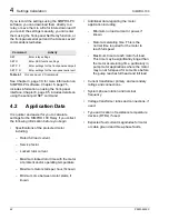
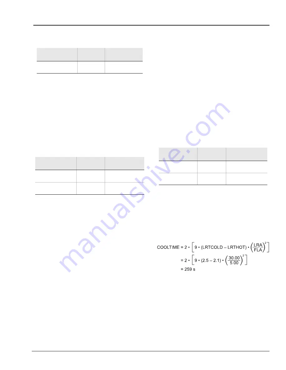
Table 4.14
Motor Cooling Time Settings
A stopped motor may take longer to cool than a
running motor due to reduced airflow or loss of
forced coolant. The factory default settings
assume that the motor stopped cooling time is
twice the motor running cooling time. Based on
the setting names, the equation is:
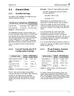
Equation 4.2
You can take similar steps to calculate the
COOLTIME setting for your application.
Motor running and stopped cooling times or time
constants may be provided by the motor
manufacturer. If a time constant is provided,
multiply that value by 3 to calculate the Motor
Stopped Cooling Time (COOLTIME) setting.
Setting Prompt
Setting
Range
Setting Name =
Factory Default
Thermal Capacity
Alarm Pickup
50% – 100%
TCAPU = 90
Setting Prompt
Setting
Range
Setting Name =
Factory Default
Thermal Capacity
Used to Start
20% – 100%
TCSTART = 85
Use Learned Starting
Thermal Capacity
Y, N
TCLRNEN = Y
Setting Prompt
Setting
Range
Setting Name =
Factory Default
Motor Stopped
Cooling Time
180 – 72000 s
COOLTIME = 259
Use Learned
Cooling Time
Y, N
COOLEN = Y
Summary of Contents for SIMPRO-100
Page 1: ...SIMPRO 100 Motor Protection Relay Instruction Manual Document No PRIM 2400C ...
Page 12: ...Contents SIMPRO 100 x PRIM 2400C ...
Page 16: ...Contents SIMPRO 100 xiv PRIM 2400C ...
Page 42: ...3 SIMPRO PC Software SIMPRO 100 40 PRIM 2400C ...
Page 100: ...6 ASCII Serial Port Operation SIMPRO 100 98 PRIM 2400C ...
Page 127: ...SIMPRO 100 Event Analysis 9 PRIM 2400C 125 Figure 9 2 Example SER Report ...
Page 136: ...10 Maintenance Troubleshooting SIMPRO 100 134 PRIM 2400C ...
Page 138: ...A Firmware Versions SIMPRO 100 136 PRIM 2400C ...
Page 206: ...D SIMPRO PC Compatibility Features SIMPRO 100 204 PRIM 2400C ...
Page 214: ...E Motor Thermal Element SIMPRO 100 212 PRIM 2400C ...
Page 230: ...F SIMPRO 100 Relay Settings Sheets SIMPRO 100 228 PRIM 2400C ...
Page 239: ......


