


4
Settings Calculation
SIMPRO-100
54
PRIM-2400C
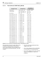
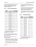
When the relay is monitoring one or more RTDs
in the motor windings and an ambient
temperature RTD, the relay can learn the stator
cooling time by monitoring the winding
temperature when the motor is stopped. If you set
Use Learned Cooling Time equal to Y, the relay
learns the cooling time over five stops and uses it
in the thermal model in place of the Motor
Stopped Cooling Time setting. When you apply
the user-defined curve Thermal Element Setting
Method (SETMETH = USER), the rotor and stator
cooling time constants for the motor may be
significantly different. Therefore, Use Learned
Cooling Time should be disabled (COOLEN = N)
in this case, unless a cooling time or time
constant is recommended by the motor
manufacturer.
4.4.2
Overcurrent Elements
If the SIMPRO-100 Relay is connected to a motor
protected by a fused contactor, disable the phase
overcurrent elements by setting their pickups to
OFF. If the relay is connected to a device capable
of interrupting fault current, use the Level 1 phase
overcurrent element to detect and trip for short
circuit faults. Set the Level 1 pickup equal to
1.2 – 1.5 times the motor locked rotor current with
a 0.10 second time delay. Set the Level 2 pickup
equal to 2.0 times the locked rotor current with a
0.00 second time delay.
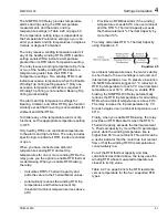
The relay offers two types of ground fault
detecting overcurrent elements. The neutral
overcurrent elements (50N1T and 50N2T)
operate using current measured by the IN input.
The residual overcurrent elements (50G1T and
50G2T) operate using the sum of the measured
phase currents.
When a ground fault CT is connected to the relay
IN input, as in Figure 2.6, page 30, use the
Level 1 ground overcurrent element to detect
motor ground faults. Calculate the pickup setting
based on the available ground fault current and
the neutral CT ratio.
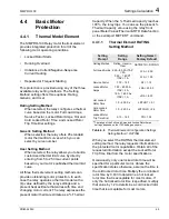
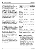
Table 4.15
Overcurrent Element Settings
Example:
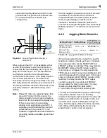
Ground Fault CT Application
A resistance-grounded transformer limits
the current for motor or cable ground faults.
The resistor is sized to limit the current to
10 A primary. The three motor leads are
passed through the window of a 10:1 CT.
The CT secondary is connected to the
SIMPRO-100 Relay 1 A IN current input, as
shown in Figure 4.4, page 55. The relay IN
input measures 1 A for a motor or cable
ground fault. Setting the Level 1 Neutral
O/C Pickup (50N1P) equal to 0.5 A with
0.10 second time delay ensures that the
Setting
Prompt
Setting Range
Setting Name =
Factory Default
Level 1 Phase
O/C Pickup
OFF, 0.25 – 100.00 A
a
50P1P = OFF
Level 1 Phase
O/C Time Delay
0.00 – 400.00 s
50P1D = 0.60
Level 2 Phase
O/C Pickup
OFF, 0.25 – 100.00 A
a
50P2P = OFF
Level 2 Phase
O/C Time Delay
0.00 – 400.00 s
50P2D = 0.50
Level 1 Residual
O/C Pickup
OFF, 0.25 – 100.00 A
a
50G1P = OFF
Level 1 Residual
O/C Time Delay
0.00 – 400.00 s
50G1D = 0.60
Level 2 Residual
O/C Pickup
OFF, 0.25 – 100.00 A
a
50G2P = OFF
Level 2 Residual
O/C Time Delay
0.00 – 400.00 s
50G2D = 0.50
Level 1 Neutral
O/C Pickup
OFF, 0.025 – 10.000 A
b
50N1P = 0.500
Level 1 Neutral
O/C Time Delay
0.00 – 400.00 s
50N1D = 0.10
Level 2 Neutral
O/C Pickup
OFF, 0.025 – 10.000 A
b
50N2P = OFF
Level 2 Neutral
O/C Time Delay
0.00 – 400.00 s
50N2D = 0.50
Negative-Seq.
O/C Pickup
OFF, 0.25 – 100.00 A
b
50QP = OFF
Negative-Seq.
O/C Time Delay
0.10 – 400.00 s
50QD = 0.60
a
Setting range shown for ITAP = 5 A. Range is 0.05 – 20.00 A when
ITAP = 1 A.
b
Setting range shown for INTAP = 5 A. Range is 0.005 – 2.000 A
when INTAP = 1 A.
Summary of Contents for SIMPRO-100
Page 1: ...SIMPRO 100 Motor Protection Relay Instruction Manual Document No PRIM 2400C ...
Page 12: ...Contents SIMPRO 100 x PRIM 2400C ...
Page 16: ...Contents SIMPRO 100 xiv PRIM 2400C ...
Page 42: ...3 SIMPRO PC Software SIMPRO 100 40 PRIM 2400C ...
Page 100: ...6 ASCII Serial Port Operation SIMPRO 100 98 PRIM 2400C ...
Page 127: ...SIMPRO 100 Event Analysis 9 PRIM 2400C 125 Figure 9 2 Example SER Report ...
Page 136: ...10 Maintenance Troubleshooting SIMPRO 100 134 PRIM 2400C ...
Page 138: ...A Firmware Versions SIMPRO 100 136 PRIM 2400C ...
Page 206: ...D SIMPRO PC Compatibility Features SIMPRO 100 204 PRIM 2400C ...
Page 214: ...E Motor Thermal Element SIMPRO 100 212 PRIM 2400C ...
Page 230: ...F SIMPRO 100 Relay Settings Sheets SIMPRO 100 228 PRIM 2400C ...
Page 239: ......


