


SIMPRO-100
Settings Calculation
4
PRIM-2400C
57
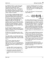
alarm or trip threshold for the specified time
delay. Set the Load Loss Trip and Alarm
thresholds greater than the expected motor no
load power but less than the minimum power
expected when the motor is operating normally.
If you expect the motor to operate at no load
normally, disable this function by setting LLAPU
equal to OFF. The relay automatically hides the
remaining load-loss settings.
4.4.6
Current Unbalance
Elements
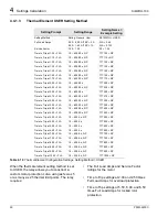
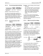
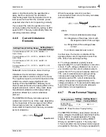
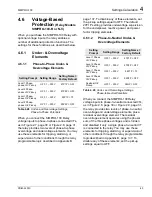
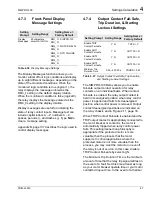
Table 4.20
Current Unbalance Element Settings
Unbalanced motor terminal voltages cause
unbalanced stator currents to flow in the motor.
The negative-sequence current component of the
unbalance current causes significant rotor
heating. While the SIMPRO-100 Relay motor
thermal element models the heating effect of the
negative-sequence current, many users desire
the additional unbalance and single-phasing
protection offered by a current unbalance
element.
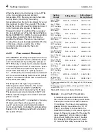
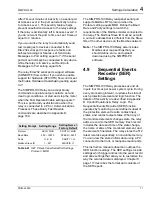
The SIMPRO-100 Relay calculates percent
unbalance current in one of two ways depending
on the magnitude of the average current. When
the average current, Iav, is greater than the
motor-rated full load current, the relay calculates
percent unbalance:
Equation 4.3
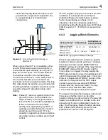
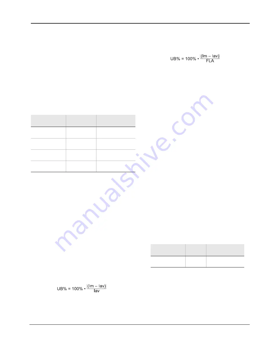
When the average current is less than
motor-rated full load current, the relay calculates
percent unbalance:
Equation 4.4
where:
UB% =Current unbalance percentage
Im =Magnitude of the phase current with
the largest deviation from average
Iav =Magnitude of the average phase
current
FLA =Motor-rated full load current
In either case, the function is disabled if the
average phase current magnitude is less than
25% of the Full Load Amps setting.
A 1% voltage unbalance typically causes
approximately 6% current unbalance in induction
motors. If a 2% voltage unbalance can occur in
your location, set the current unbalance alarm
greater than 12% to prevent nuisance alarms. A
15% current unbalance alarm pickup setting
corresponds to approximately 2.5% voltage
unbalance and a 20% current unbalance trip
setting corresponds to approximately 3.3%
voltage unbalance. A 10-second alarm delay and
5-second trip delay should provide adequate
performance in most applications.
4.4.7
Phase Reversal Tripping
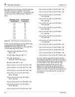
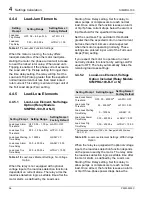
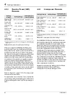
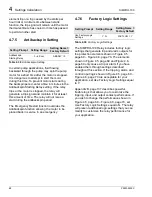
Table 4.21
Phase Reversal Tripping Setting
The SIMPRO-100 Relay uses phase currents or
phase voltages (if available) to determine that the
phase rotation of signals applied to the relay
matches the phase rotation setting, PHROT.
When you set E47T equal to Y, the relay trips
0.5 seconds after incorrect phase rotation signals
are applied to the relay. For relays equipped with
Setting Prompt Setting Range
Setting Name =
Example Settings
Current Unbalance
Alarm Pickup
OFF, 2% – 80% 46UBA = 15
Current Unbalance
Alarm Delay
0.10 – 400.00 s 46UBAD = 10.00
Current Unbalance
Trip Pickup
OFF, 2% – 80% 46UBT = 20
Current Unbalance
Trip Delay
0.10 – 400.00 s 46UBTD = 5.00
Setting Prompt
Setting
Range
Setting Name =
Factory Default
Enable Phase
Reversal Tripping
Y, N
E47T = Y
Summary of Contents for SIMPRO-100
Page 1: ...SIMPRO 100 Motor Protection Relay Instruction Manual Document No PRIM 2400C ...
Page 12: ...Contents SIMPRO 100 x PRIM 2400C ...
Page 16: ...Contents SIMPRO 100 xiv PRIM 2400C ...
Page 42: ...3 SIMPRO PC Software SIMPRO 100 40 PRIM 2400C ...
Page 100: ...6 ASCII Serial Port Operation SIMPRO 100 98 PRIM 2400C ...
Page 127: ...SIMPRO 100 Event Analysis 9 PRIM 2400C 125 Figure 9 2 Example SER Report ...
Page 136: ...10 Maintenance Troubleshooting SIMPRO 100 134 PRIM 2400C ...
Page 138: ...A Firmware Versions SIMPRO 100 136 PRIM 2400C ...
Page 206: ...D SIMPRO PC Compatibility Features SIMPRO 100 204 PRIM 2400C ...
Page 214: ...E Motor Thermal Element SIMPRO 100 212 PRIM 2400C ...
Page 230: ...F SIMPRO 100 Relay Settings Sheets SIMPRO 100 228 PRIM 2400C ...
Page 239: ......


