


SIMPRO-100
Settings Calculation
4
PRIM-2400C
63
4.6
Voltage-Based
Protection
(Relay Models
SIMPRO-100-R or N-V)
When you purchase the SIMPRO-100 Relay with
optional voltage inputs, the relay enables a
number of additional protection functions. The
settings for these functions are described below.
4.6.1
Under- & Overvoltage
Elements
4.6.1.1
Phase-to-Phase Under- &
Overvoltage Elements
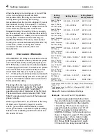
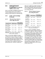
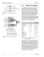
Table 4.28
Under- and Overvoltage Settings,
Phase-to-Phase Potentials
When you connect the SIMPRO-100 Relay
voltage inputs to phase-to-phase connected VTs,
as in Figure 2.7, page 30 or Figure 2.8, page 31,
the relay provides two levels of phase-to-phase
overvoltage and undervoltage elements. You may
use these elements for tripping, alarming, or
supervision of other conditions through the relay
programmable logic described in Appendix B,
page 137. To disable any of these elements, set
the pickup settings equal to OFF. The default
27P1P setting provides undervoltage supervision
for the underpower, reactive power, and power
factor tripping elements.
4.6.1.2
Phase-to-Neutral Under- &
Overvoltage Elements
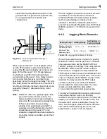
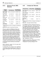
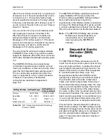
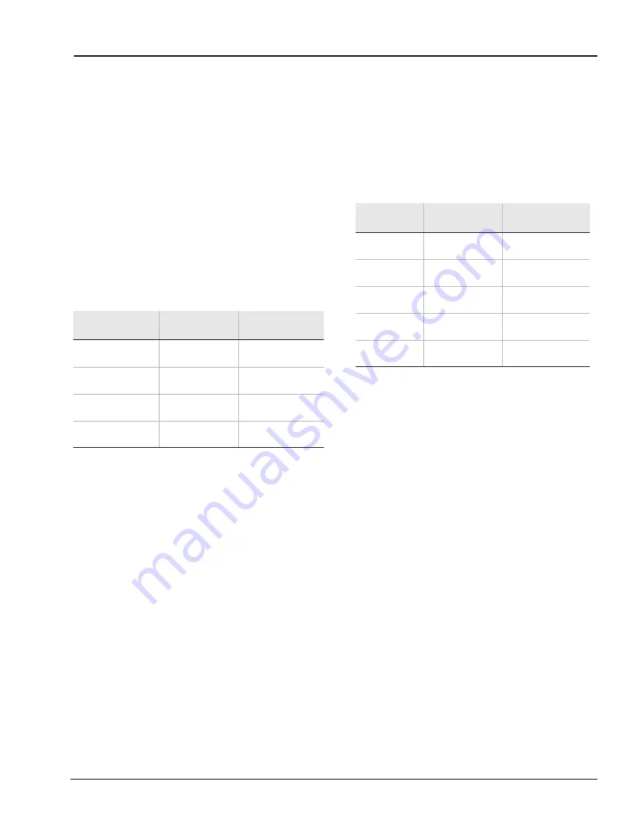
Table 4.29
Under- and Overvoltage Settings,
Phase-to-Neutral Potentials
When you connect the SIMPRO-100 Relay
voltage inputs to phase-to-neutral connected VTs,
as in Figure 2.6, page 30 or Figure 2.9, page 31,
the relay provides two levels of phase-to-neutral
overvoltage and undervoltage elements, plus a
residual overvoltage element. The residual
overvoltage element operates using the phasor
sum of the three phase voltages and is hidden
and disabled if only a single phase-to-neutral VT
is connected to the relay. You may use these
elements for tripping, alarming, or supervision of
other conditions through the relay programmable
logic described in Appendix B, page 137. To
disable any of these elements, set the pickup
settings equal to OFF.
Setting Prompt Setting Range
Setting Name =
Factory Default
Level 1 Phase-
phase U/V Pickup
OFF, 1 – 300 V
27P1P = OFF
Level 2 Phase-
phase U/V Pickup
OFF, 1 – 300 V
27P2P = OFF
Level 1 Phase-
phase O/V Pickup
OFF, 1 – 300 V
59P1P = 73
Level 2 Phase-
phase O/V Pickup
OFF, 1 – 300 V
59P2P = OFF
Setting
Prompt
Setting Range
Setting Name =
Factory Default
Level 1 Phase
U/V Pickup
OFF, 1 – 300 V
27P1P = OFF
Level 2 Phase
U/V Pickup
OFF, 1 – 300 V
27P2P = OFF
Level 1 Phase
O/V Pickup
OFF, 1 – 300 V
59P1P = 73
Level 2 Phase
O/V Pickup
OFF, 1 – 300 V
59P2P = OFF
Residual O/V
Pickup
OFF, 1 – 300 V
59GP = OFF
Summary of Contents for SIMPRO-100
Page 1: ...SIMPRO 100 Motor Protection Relay Instruction Manual Document No PRIM 2400C ...
Page 12: ...Contents SIMPRO 100 x PRIM 2400C ...
Page 16: ...Contents SIMPRO 100 xiv PRIM 2400C ...
Page 42: ...3 SIMPRO PC Software SIMPRO 100 40 PRIM 2400C ...
Page 100: ...6 ASCII Serial Port Operation SIMPRO 100 98 PRIM 2400C ...
Page 127: ...SIMPRO 100 Event Analysis 9 PRIM 2400C 125 Figure 9 2 Example SER Report ...
Page 136: ...10 Maintenance Troubleshooting SIMPRO 100 134 PRIM 2400C ...
Page 138: ...A Firmware Versions SIMPRO 100 136 PRIM 2400C ...
Page 206: ...D SIMPRO PC Compatibility Features SIMPRO 100 204 PRIM 2400C ...
Page 214: ...E Motor Thermal Element SIMPRO 100 212 PRIM 2400C ...
Page 230: ...F SIMPRO 100 Relay Settings Sheets SIMPRO 100 228 PRIM 2400C ...
Page 239: ......


