


4
Settings Calculation
SIMPRO-100
64
PRIM-2400C
4.6.2
Reactive Power (VAR)
Elements
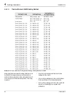
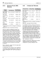
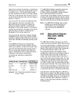
Table 4.30
Reactive Power Element Settings
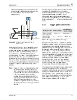
When you apply the SIMPRO-100 Relay on a
synchronous motor, the VAR Element Arming
Delay disarms the reactive power elements for a
settable time after the motor starts. This allows
the motor to be brought to full speed and the field
applied. After the VAR Element Arming Delay
expires, the VAR Alarm and VAR Trip elements
are enabled. If the positive or negative reactive
power exceeds the appropriate threshold for
longer than the time delay setting, the relay can
issue an alarm or trip signal. The reactive power
elements are disabled when the motor is stopped
or starting. These elements can be used to detect
synchronous motor out-of-step or loss-of-field
conditions.
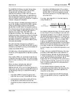
Refer to Figure 8.1, page 113 for the relay power
measurement convention.
For application on an induction motor, disable the
elements by setting both the Negative VAR Alarm
Pickup and Negative VAR Trip Pickup settings to
OFF.
4.6.3
Underpower Elements
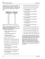
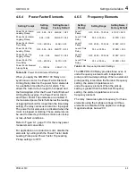
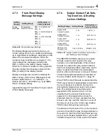
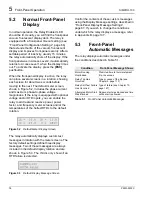
Table 4.31
Underpower Element Settings
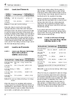
The SIMPRO-100 Relay Underpower Element
Arming Delay disarms the underpower elements
for a settable time after the motor starts. This
allows the motor to be brought to full load. After
the Underpower Element Arming Delay expires,
the Phase Underpower Alarm and Phase
Underpower Trip elements are enabled. If the
real three-phase power falls below the alarm or
trip threshold for longer than the time delay
setting, the relay can issue an alarm or trip signal.
The underpower elements are disabled when the
motor is stopped or starting. These elements
operate in addition to the Load Loss function and
you can use them to detect motor load loss and
other underpower conditions.
Disable the elements by setting both the Phase
Underpower Alarm Pickup and Phase
Underpower Trip Pickup settings to OFF.
Setting
Prompt
Setting Range
Setting Name =
Factory Default
Negative VAR
Alarm Pickup
OFF, 30 – 2000 VAR
a
NVARAP = OFF
Positive VAR
Alarm Pickup
30 – 2000 VAR
a
PVARAP = 2000
VAR Alarm Time
Delay
0.00 – 400.00 s
VARAD = 0.00
Negative VAR
Trip Pickup
OFF, 30 – 2000 VAR
a
NVARTP = OFF
Positive VAR
Trip Pickup
30 – 2000 VAR
a
PVARTP = 2000
VAR Trip Time
Delay
0.00 – 400.00 s
VARTD = 0.00
VAR Element
Arming Delay
0 – 15000 s
VARDLY = 10
a
Setting range shown for ITAP = 5 A. Range is 6 – 400 VAR when
ITAP = 1 A.
Setting Prompt
Setting Range
Setting Name =
Factory Default
Phase Underpower
Alarm Pickup
OFF, 30
–
2000 W
a
37PAP = OFF
Phase Underpower
Alarm Time Delay
0.00
–
400.00 s
37PAD = 0.00
Phase Underpower
Trip Pickup
OFF, 30
–
2000 W
a
37PTP = OFF
Phase Underpower
Trip Time Delay
0.00
–
400.00 s
37PTD = 0.00
Underpower
Element Arming
Delay
0
–
15000 s
37DLY = 10
a
Setting range shown for ITAP = 5 A. Range is 6 – 400 W when
ITAP = 1 A.
Summary of Contents for SIMPRO-100
Page 1: ...SIMPRO 100 Motor Protection Relay Instruction Manual Document No PRIM 2400C ...
Page 12: ...Contents SIMPRO 100 x PRIM 2400C ...
Page 16: ...Contents SIMPRO 100 xiv PRIM 2400C ...
Page 42: ...3 SIMPRO PC Software SIMPRO 100 40 PRIM 2400C ...
Page 100: ...6 ASCII Serial Port Operation SIMPRO 100 98 PRIM 2400C ...
Page 127: ...SIMPRO 100 Event Analysis 9 PRIM 2400C 125 Figure 9 2 Example SER Report ...
Page 136: ...10 Maintenance Troubleshooting SIMPRO 100 134 PRIM 2400C ...
Page 138: ...A Firmware Versions SIMPRO 100 136 PRIM 2400C ...
Page 206: ...D SIMPRO PC Compatibility Features SIMPRO 100 204 PRIM 2400C ...
Page 214: ...E Motor Thermal Element SIMPRO 100 212 PRIM 2400C ...
Page 230: ...F SIMPRO 100 Relay Settings Sheets SIMPRO 100 228 PRIM 2400C ...
Page 239: ......


