


4
Settings Calculation
SIMPRO-100
72
PRIM-2400C
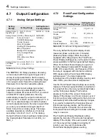
4.9.1
SER Trigger Settings
Table 4.42
SET R SER Trigger Settings
The SIMPRO-100 Relay SER function provides
four list settings to define the conditions that add
records to the SER memory: SER1, SER2,
SER3, and SER4. You can set the relay to
monitor up to 96 conditions. Each list can contain
up to 24 items. Each item must be the name of a
Relay Word bit whose definitions are shown in
Table B.4 on page 151. The factory default SER
settings are shown in Table 4.42.
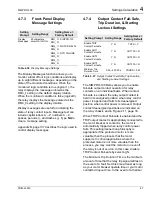
For convenience, and because you may not need
to make any changes to the factory default
settings above, the definitions of the Relay Word
bits used in the factory default SER settings are
shown in Table 4.43.
Setting
Prompt
Setting Range
Setting Name = Factory Default
SER1
24 Relay Word bits, separated by
commas. Use NA to disable setting.
SER1 = IN1, IN2, IN3, IN4, IN5, IN6, IN7
SER2
24 Relay Word bits, separated by
commas. Use NA to disable setting.
SER2 = STARTING, RUNNING, STOPPED, JAMTRIP, LOSSALRM,
LOSSTRIP, 46UBA, 46UBT, 49A, 49T, 47T, SPEEDSW, SPDSTR, TRIP, OUT1,
OUT2, OUT3, 50G1T, 50G2T, 50N1T, 50N2T
SER3
24 Relay Word bits, separated by
commas. Use NA to disable setting.
SER3 = RTDFLT, WDGALRM, WDGTRIP, BRGALRM, BRGTRIP, AMBALRM,
AMBTRIP, OTHALRM, OTHTRIP, 81D1T, 81D2T, 81D3T, TRGTR, START,
50P1T, 50P2T
SER4
24 Relay Word bits, separated by
commas. Use NA to disable setting.
SER4 = NA
Relay Word Bits
Relay Word Bit Definitions
IN1, IN2, IN3, IN4, IN5,
IN6, IN7
Represent the state of contact inputs IN1-IN7, respectively. Assert (Logical 1) when the input detects
that the contact connected to it is closed.
STARTING, RUNNING,
STOPPED
Represent the states of the protected motor.
JAMTRIP
Load Jam Trip.
Asserts when the relay trips in response to a load jam condition, as defined by that
function. This Relay Word bit is inactive if the load jam function is disabled.
LOSSALRM, LOSSTRIP
Load Loss Alarm and Load Loss Trip.
Assert when the relay issues an alarm or trip in response to
a load loss condition, as defined by that function. These Relay Word bits are inactive if the load loss
function is disabled.
46UBA, 46UBT
Phase Current Unbalance Alarm (46UBA) and Trip (46UBT).
Assert when the relay issues an
alarm or trip in response to a current unbalance condition, as defined by that function. These Relay
Word bits are inactive if the current unbalance function is disabled.
49A, 49T
Thermal Alarm and Trip.
Assert when the relay issues a thermal element alarm or trip due to
locked rotor or running overload conditions.
47T
Phase Reversal Trip.
Asserts when the relay detects a phase reversal condition if phase reversal
tripping is enabled by the relay settings.
SPEEDSW, SPDSTR
Speed Switch Input and Trip.
SPEEDSW asserts when the speed switch input is asserted.
SPDSTR asserts when the relay does not detect a speed switch contact closure within a settable
time from the beginning of a motor start if the function is enabled by the relay settings.
Summary of Contents for SIMPRO-100
Page 1: ...SIMPRO 100 Motor Protection Relay Instruction Manual Document No PRIM 2400C ...
Page 12: ...Contents SIMPRO 100 x PRIM 2400C ...
Page 16: ...Contents SIMPRO 100 xiv PRIM 2400C ...
Page 42: ...3 SIMPRO PC Software SIMPRO 100 40 PRIM 2400C ...
Page 100: ...6 ASCII Serial Port Operation SIMPRO 100 98 PRIM 2400C ...
Page 127: ...SIMPRO 100 Event Analysis 9 PRIM 2400C 125 Figure 9 2 Example SER Report ...
Page 136: ...10 Maintenance Troubleshooting SIMPRO 100 134 PRIM 2400C ...
Page 138: ...A Firmware Versions SIMPRO 100 136 PRIM 2400C ...
Page 206: ...D SIMPRO PC Compatibility Features SIMPRO 100 204 PRIM 2400C ...
Page 214: ...E Motor Thermal Element SIMPRO 100 212 PRIM 2400C ...
Page 230: ...F SIMPRO 100 Relay Settings Sheets SIMPRO 100 228 PRIM 2400C ...
Page 239: ......


