


5
Front-Panel Operation
SIMPRO-100
76
PRIM-2400C
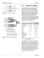
5.2
Normal Front-Panel
Display
In normal operation, the Relay Enabled LED
should be lit. Usually, you will find the front-panel
vacuum fluorescent display dark. The relay is
equipped with a front-panel timeout setting (see
“Front-Panel Configuration Settings”, page 66)
that extends the life of the vacuum fluorescent
display and improves front-panel security. After a
settable period of inactivity, usually 15 minutes,
the relay automatically shuts off the display. If the
front panel was in Access Level 2, it automatically
returns to Access Level 1 when the display times
out. To activate the display, press the
{ESC}
pushbutton.
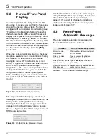
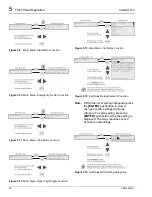
When the front-panel display is active, the relay
can place several screens in a rotation, showing
each screen for about two seconds before
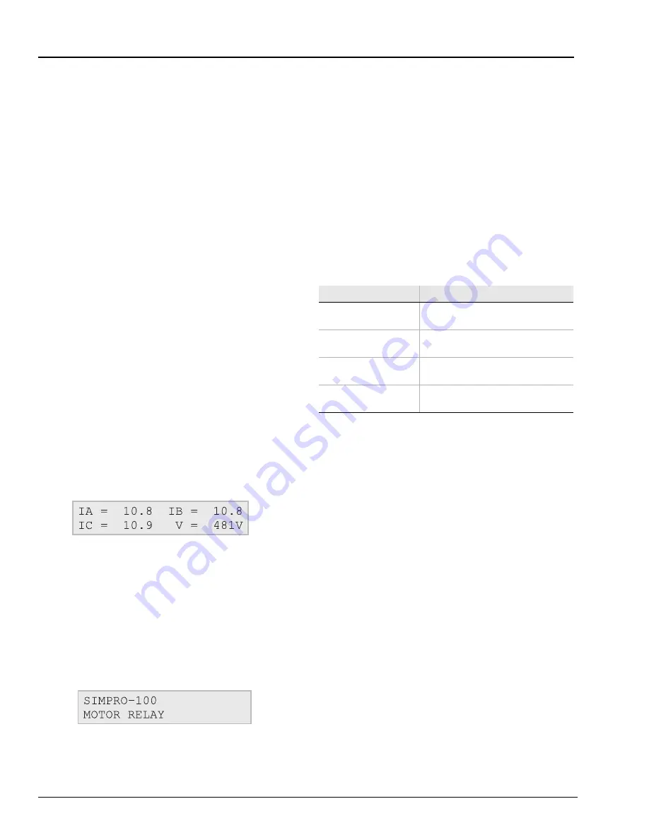
moving to the next. The default meter screen,
shown in Figure 5.2, includes the phase current
and maximum phase-to-phase voltage
magnitudes. If the relay is equipped with optional
voltage and/or RTD inputs, you can enable the
relay to add real and reactive power, power
factor, and frequency meter screens and/or the
temperatures of the hottest RTDs to the default
rotation.
Figure 5.2
Default Meter Display Screen
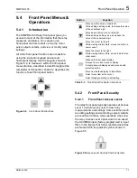
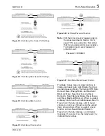
The relay automatically displays custom text
messages in rotation with the meter screens. The
factory default settings define three display
messages. Two of these messages are always
included in the default display rotation and are
shown in Figure 5.3. The third is only shown if an
RTD failure is detected.
Figure 5.3
Default Display Message Screen
Control the contents of these custom messages
using the Display Message settings, described in
“Front-Panel Display Message Settings”,
page 67. If you wish to change the conditions
under which the relay displays a message, refer
to Appendix B, page 137.
5.3
Front-Panel
Automatic Messages
The relay displays automatic messages under
the conditions described in Table 5.1.
Table 5.1
Front-Panel Automatic Messages
Condition
Front-Panel Message Shows
Motor Running
Overloaded
Predicted time to thermal element
trip, in seconds
Relay Trip Has
Occurred
Type or cause of the trip (see
Relay Self-Test Failure
Has Occurred
Type of failure (see Chapter 10,
Attempted Motor Start
Was Blocked
Reason start was blocked and time
until a start is allowed
Summary of Contents for SIMPRO-100
Page 1: ...SIMPRO 100 Motor Protection Relay Instruction Manual Document No PRIM 2400C ...
Page 12: ...Contents SIMPRO 100 x PRIM 2400C ...
Page 16: ...Contents SIMPRO 100 xiv PRIM 2400C ...
Page 42: ...3 SIMPRO PC Software SIMPRO 100 40 PRIM 2400C ...
Page 100: ...6 ASCII Serial Port Operation SIMPRO 100 98 PRIM 2400C ...
Page 127: ...SIMPRO 100 Event Analysis 9 PRIM 2400C 125 Figure 9 2 Example SER Report ...
Page 136: ...10 Maintenance Troubleshooting SIMPRO 100 134 PRIM 2400C ...
Page 138: ...A Firmware Versions SIMPRO 100 136 PRIM 2400C ...
Page 206: ...D SIMPRO PC Compatibility Features SIMPRO 100 204 PRIM 2400C ...
Page 214: ...E Motor Thermal Element SIMPRO 100 212 PRIM 2400C ...
Page 230: ...F SIMPRO 100 Relay Settings Sheets SIMPRO 100 228 PRIM 2400C ...
Page 239: ......


