


6
ASCII Serial Port Operation
SIMPRO-100
96
PRIM-2400C
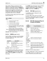
6.8.37
STATUS R
(Level 2)
To reset the self-test status and restart the relay,
use the
STA R
command from Access Level 2.
The relay then restarts (just like powering down,
then powering up the relay) and all diagnostics
are rerun before the relay is enabled.
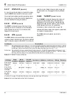
6.8.38
STOP
(Level 2)
The
STOP
command causes the relay to trip,
opening the motor contactor or circuit breaker
and stopping the motor. The command also
triggers an event report.
6.8.39
STR
(Level 2)
The
STR
(Start) command initiates a motor start
using the relay’s internal logic. The factory default
logic configures output contact OUT3 too close to
start the motor. Refer to Section B.5, page 144
for information on changing the factory default
logic.
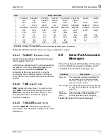
6.8.40
TARGET
(Level 1 or 2)
The
TARGET
command displays the status of
relay elements whether they are asserted or
deasserted. The elements are represented as
Relay Word bits and are listed in rows of eight,
called Relay Word rows. For additional
information, refer to Section B.3, page 138.
A Relay Word bit is either at a logical 1 (asserted)
or a logical 0 (deasserted).
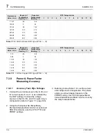
The
TAR
command options are listed in
Table 6.17
TARGET Command Options
Table 6.18
Front-Panel LEDs & the TAR 0 Command
Commands
Descriptions
TAR n k
Shows Relay Word row number n (0 – 11). k is an optional parameter to specify the number of times (1 – 32767)
to repeat the Relay Word row display. If k is not specified, the Relay Word row is displayed once. SeeTable 6.18
for definition of Row 0. See Table 6.19 for a list of the Relay Word bits in each row (n = 1 – 10).
TAR name k Shows Relay Word row containing Relay Word bit name (e.g., TAR 50P1T displays Relay Word Row 3). Valid
names are shown in Table 6.18. k is an optional parameter to specify the number of times (1 – 32767) to repeat
the Relay Word row display. If k is not specified, the Relay Word row is displayed once.
LED Name
Relay
Enabled
Motor
Energized
Thermal
Overload
Overcurrent Unbalance Load Loss Voltage Frequency
When LED is
Dark, TAR 0
Displays
ENABLE
0
MOTRUN
0
THERM_OL
0
OVERCURR
0
UNBAL
0
LOADLOSS
0
VOLTAGE
0
FREQ
0
When LED is
Flashing, TAR
0 Displays
-
MOTSTART
1
THERM_AL
1
-
UNBAL_AL
1
LOSS_AL
1
VOLT_AL
1
-
When LED is
On, TAR 0
Displays
ENABLE
1
MOTRUN
1
THERM_OL
1
OVERCURR
1
UNBAL
1
LOADLOSS
1
VOLTAGE
1
FREQ
1
a See Table 9.1 on page 117 for additional information on the meaning of each target LED condition.
Summary of Contents for SIMPRO-100
Page 1: ...SIMPRO 100 Motor Protection Relay Instruction Manual Document No PRIM 2400C ...
Page 12: ...Contents SIMPRO 100 x PRIM 2400C ...
Page 16: ...Contents SIMPRO 100 xiv PRIM 2400C ...
Page 42: ...3 SIMPRO PC Software SIMPRO 100 40 PRIM 2400C ...
Page 100: ...6 ASCII Serial Port Operation SIMPRO 100 98 PRIM 2400C ...
Page 127: ...SIMPRO 100 Event Analysis 9 PRIM 2400C 125 Figure 9 2 Example SER Report ...
Page 136: ...10 Maintenance Troubleshooting SIMPRO 100 134 PRIM 2400C ...
Page 138: ...A Firmware Versions SIMPRO 100 136 PRIM 2400C ...
Page 206: ...D SIMPRO PC Compatibility Features SIMPRO 100 204 PRIM 2400C ...
Page 214: ...E Motor Thermal Element SIMPRO 100 212 PRIM 2400C ...
Page 230: ...F SIMPRO 100 Relay Settings Sheets SIMPRO 100 228 PRIM 2400C ...
Page 239: ......


