7
Commissioning
SIMPRO-100
106
PRIM-2400C
7.3.5
Motor Thermal Element
Accuracy
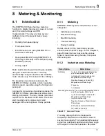
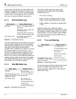
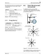
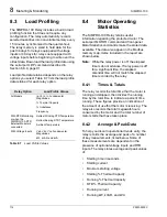
Note:
This test outlines steps to verify
performance of any of the GENERIC
thermal curves. When using the RATING
or USER thermal element setting
methods, the steps are similar, but the
expected operating times will be different,
depending on the settings you use.
1. Connect the current sources to the IA, IB, and
IC current inputs (5 A or 1 A, as indicated by
the ITAP setting).
2. Using the front-panel Set Relay\Relay
Elements\Thermal Model Elements function
or serial port SHOW command, note the
PHROT, FLA, and CURVE settings. Set the
Service Factor setting, SF equal to 1.15.
Note:
Changing settings requires that you
enter the Access Level 2 password.
The factory password is 100.
3. Set the current source phase angles to apply
balanced three-phase currents. Refer to
Figure 7.1, page 100 for the correct angles,
which depend on the PHROT setting.
4. Reset the motor thermal element using the
front-panel Reset Thermal Model function.
Note:
This function requires that you enter
the Access Level 2 password. The
factory password is 100.
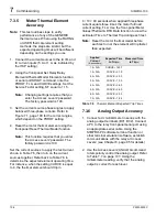
Set the current sources to apply the test current
shown in Table 7.6, then turn on the current
sources together. Refer back to Table 7.6 to
determine the expected element operating time.
For instance, when the setting CURVE is equal
to 4, the thermal element should trip in
4 • 10 = 40 seconds when applied three-phase
current equals three times the motor full load
current setting, FLA. Use the front-panel Meter
Values\Thermal & RTD Data function to view the
estimated Time to Thermal Trip during each test.
Note:
Reset the motor thermal model before
each test run or the element will trip faster
than expected.
Table 7.6
Thermal Element Expected Trip Times
7.3.6
Analog Output Accuracy
1. Connect a dc milliammeter in series with the
analog output terminals (B01, B02). Connect
a PC to the relay front-panel serial port using
an appropriate serial cable. Using the
SIMPRO-PC software terminal function or
other terminal emulation software, establish
communications with the relay at Access
Level 2 (see Chapter 6, page 85 for details).
2. Use the Access Level 2 ANALOG command
to temporarily control the analog output. Refer
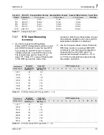
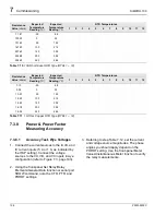
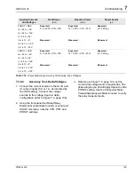
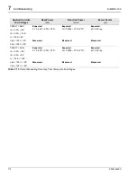
to Table 7.7 on page 107. Using the
milliammeter reading, verify that the analog
output is correct for each level.
Applied
Current
(A secondary)
Expected Time
to Trip
(s)
Measured Time
to Trip
(s)
1.2 • FLA
CURVE • 145.7
1.5 • FLA
CURVE • 51.5
2.0 • FLA
CURVE • 23.3
3.0 • FLA
CURVE • 10.0
4.0 • FLA
CURVE • 5.63
5.0 • FLA
CURVE • 3.60
6.0 • FLA
CURVE • 2.50
7.0 • FLA
CURVE • 1.84
Summary of Contents for SIMPRO-100
Page 1: ...SIMPRO 100 Motor Protection Relay Instruction Manual Document No PRIM 2400C ...
Page 12: ...Contents SIMPRO 100 x PRIM 2400C ...
Page 16: ...Contents SIMPRO 100 xiv PRIM 2400C ...
Page 42: ...3 SIMPRO PC Software SIMPRO 100 40 PRIM 2400C ...
Page 100: ...6 ASCII Serial Port Operation SIMPRO 100 98 PRIM 2400C ...
Page 127: ...SIMPRO 100 Event Analysis 9 PRIM 2400C 125 Figure 9 2 Example SER Report ...
Page 136: ...10 Maintenance Troubleshooting SIMPRO 100 134 PRIM 2400C ...
Page 138: ...A Firmware Versions SIMPRO 100 136 PRIM 2400C ...
Page 206: ...D SIMPRO PC Compatibility Features SIMPRO 100 204 PRIM 2400C ...
Page 214: ...E Motor Thermal Element SIMPRO 100 212 PRIM 2400C ...
Page 230: ...F SIMPRO 100 Relay Settings Sheets SIMPRO 100 228 PRIM 2400C ...
Page 239: ......

