SIMPRO-100
Control Equations & Relay Logic
B
PRIM-2400C
137
B Control Equations & Relay Logic
B.1
Introduction
The SIMPRO-100 Relay is equipped with
programmable logic so you can customize
various relay functions. Use the programmable
logic components described in this appendix to
modify the factory default logic settings discussed
in Chapter 4, page 41. This appendix also
describes control equations and their various
applications within the SIMPRO-100 Relay.
Specific topics include:
•
General Operation of the Relay
•
Relay Word Bits
•
Control Equations
•
Front-Panel Display Configuration Settings
•
Nondedicated Control Equation Variables
•
Latching Variables
•
Stop/Trip Logic
•
Breaker Auxiliary Contact Input
•
Start and Emergency Restart Logic
•
ACCESS2 Input Logic
•
Speed Switch Contact Input
•
Event Triggering
•
Output Contact Control
•
Remote Control Functions
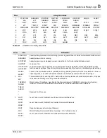
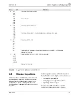
Table B.1 on page 139 and Table B.2 on
page 141 summarize all the Relay Word bits. Use
the Relay Word bits to create control equation
settings. Figures in this section summarize the
operation of many protection elements.
B.2
Relay Functional
Overview
Understanding the relay’s internal processes
makes it easier to understand the relay’s
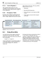
programmable logic capabilities. Figure B.1,
page 138 illustrates these processes.
B.2.1
Data Acquisition & Filtering
The SIMPRO-100 Relay passes ac current and (if
included) voltage signals through low-pass filters
to remove signals above the eighth harmonic.
Then the relay digitally samples the signals
16 times per power system cycle. The relay
automatically tracks system frequency over the
range of 20 – 70 Hz to ensure that exactly
16 samples are taken every cycle.
Four times per power system cycle, the relay
processes the sampled data using a digital filter
that further removes unwanted signals, leaving
the desired fundamental frequency data for
protection calculations. At this time, the relay also
checks the contact inputs to determine if any are
asserted.
B.2.2
Element Processing
Having acquired and filtered the ac signals, the
relay performs the enabled protection algorithms
to determine if protection elements are picked up
or dropped out.
B.2.3
Relay Word
Each relay element is represented internally as a
logic point, called a Relay Word bit. Each Relay
Word bit exists in one of two states: true or false,
picked up or dropped out. The relay uses these
results to evaluate fixed logic and the
programmable control equations defined in the
relay settings. For further details see Relay Word
Bits.
Summary of Contents for SIMPRO-100
Page 1: ...SIMPRO 100 Motor Protection Relay Instruction Manual Document No PRIM 2400C ...
Page 12: ...Contents SIMPRO 100 x PRIM 2400C ...
Page 16: ...Contents SIMPRO 100 xiv PRIM 2400C ...
Page 42: ...3 SIMPRO PC Software SIMPRO 100 40 PRIM 2400C ...
Page 100: ...6 ASCII Serial Port Operation SIMPRO 100 98 PRIM 2400C ...
Page 127: ...SIMPRO 100 Event Analysis 9 PRIM 2400C 125 Figure 9 2 Example SER Report ...
Page 136: ...10 Maintenance Troubleshooting SIMPRO 100 134 PRIM 2400C ...
Page 138: ...A Firmware Versions SIMPRO 100 136 PRIM 2400C ...
Page 206: ...D SIMPRO PC Compatibility Features SIMPRO 100 204 PRIM 2400C ...
Page 214: ...E Motor Thermal Element SIMPRO 100 212 PRIM 2400C ...
Page 230: ...F SIMPRO 100 Relay Settings Sheets SIMPRO 100 228 PRIM 2400C ...
Page 239: ......

