SIMPRO-100
Settings Calculation
4
PRIM-2400C
41
4 Settings Calculation
4.1
Introduction
The SIMPRO-100 Relay protection settings are
divided into two major categories. The first
category, described in this section, includes
settings to configure the motor protection
elements and basic functions. The second
category, described in Appendix B, page 137,
includes logic settings that allow you, if you wish,
to customize the relay contact input and output
operation. The relay also includes settings that
control the function of the serial ports and the
sequential events recorder (SER) function.
Note:
Each SIMPRO-100 Relay is shipped with
default factory settings summarized in
Appendix F, page 213. Calculate and
enter settings for your motor to ensure
that the relay provides secure,
dependable protection.
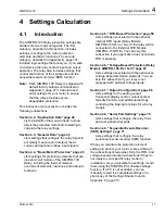
This instruction manual section includes the
following subsections:
Section 4.2, "Application Data" page 42
Lists information that you will need to know
about the protected motor before starting to
calculate the relay settings.
Section 4.3, "General Data" page 43
Lists settings that configure the relay inputs to
accurately measure and interpret the ac
current and optional voltage input signals.
Section 4.4, "Basic Motor Protection" page 45
Lists settings for protection elements that are
included in all models of the SIMPRO-100
Relay, including the thermal element,
overcurrent elements, load-loss, and load-jam
functions.
Section 4.5, "RTD-Based Protection" page 58
Lists settings associated with the optional
internal RTD inputs (Relay Models
SIMPRO-100-R-V or N) or if the relay will be
connected to the External RTD Module
(SIMPRO-100-RTD). You can skip this
subsection if your application does not include
RTD measuring.
Section 4.6, "Voltage-Based Protection (Relay
Models SIMPRO-100-R or N-V)" page 63
Lists settings associated with the optional ac
voltage-based protection elements. You can
skip this subsection if your relay is not
equipped with optional voltage inputs.
Section 4.7, "Output Configuration" page 66
Lists settings for the analog output,
front-panel display control, output contact
fail-safe function, and additional settings
controlling the tripping functions for all relay
models.
Section 4.8, "Serial Port Settings" page 70
Lists settings that configure the relay front-
and rear-panel serial ports.
Section 4.9, "Sequential Events Recorder
(SER) Settings" page 71
Lists settings that configure the relay
sequential events recorder (SER) function.
When you calculate the protection element
settings to protect your motor, proceed through
the subsections listed earlier. Skip the RTD- and
voltage-based protection subsections if they do
not apply to your specific relay model or
installation. As you calculate the settings, record
them using the SIMPRO-PC software settings
function. If a PC is not available, you can
manually record the calculated settings on a
photocopy of the Settings Sheets found in
Appendix F, page 213.
Summary of Contents for SIMPRO-100
Page 1: ...SIMPRO 100 Motor Protection Relay Instruction Manual Document No PRIM 2400C ...
Page 12: ...Contents SIMPRO 100 x PRIM 2400C ...
Page 16: ...Contents SIMPRO 100 xiv PRIM 2400C ...
Page 42: ...3 SIMPRO PC Software SIMPRO 100 40 PRIM 2400C ...
Page 100: ...6 ASCII Serial Port Operation SIMPRO 100 98 PRIM 2400C ...
Page 127: ...SIMPRO 100 Event Analysis 9 PRIM 2400C 125 Figure 9 2 Example SER Report ...
Page 136: ...10 Maintenance Troubleshooting SIMPRO 100 134 PRIM 2400C ...
Page 138: ...A Firmware Versions SIMPRO 100 136 PRIM 2400C ...
Page 206: ...D SIMPRO PC Compatibility Features SIMPRO 100 204 PRIM 2400C ...
Page 214: ...E Motor Thermal Element SIMPRO 100 212 PRIM 2400C ...
Page 230: ...F SIMPRO 100 Relay Settings Sheets SIMPRO 100 228 PRIM 2400C ...
Page 239: ......

