SIMPRO-100
Settings Calculation
4
PRIM-2400C
71
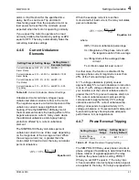
After Timeout minutes of inactivity on a serial port
at Access Level 2, the port automatically returns
to Access Level 1. This security feature helps
prevent unauthorized access to the relay settings
if the relay is accidentally left in Access Level 2. If
you do not want the port to time out, set Timeout
equal to 0 minutes.
If you would like the relay to automatically send
text messages to devices connected to the
EIA-232 serial port in response to faults and
self-test warnings or failures, set Send Auto
Messages to Port setting equal to Y. If the serial
port will not normally be connected to any device
while the relay is in service, set Send Auto
Messages to Port setting equal to N.
The relay EIA-232 serial ports support software
(XON/XOFF) flow control. If you wish to enable
support for hardware (RTS/CTS) flow control, set
the Enable Hardware Handshaking setting equal
to Y.
The SIMPRO-100 Relay can accept binary
commands to operate output contacts, set and
clear logic conditions, or start and stop the motor
when the Fast Operate Enable setting equals Y.
This is a particularly useful function when the
relay is connected to a PC or Communications
Processor. These binary Fast Operate
commands are described in Appendix D,
page 189.
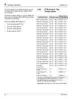
Table 4.41
SET P Rear-Panel Serial Port Settings,
Protocol = MOD
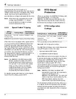
The SIMPRO-100 Relay rear-panel serial port
supports Modbus RTU protocol when the
Protocol setting equals MOD. Define the Baud
Rate and Parity settings to match the
requirements of the Modbus master connected to
the relay. The Modbus Slave ID must be set with
a numeric address that is different from the Slave
IDs of the other devices on the Modbus network.
Note:
The SIMPRO-100 Relay also includes
Modbus user map settings that you
should define, store, and upload/
download using the SIMPRO-PC
software.
4.9
Sequential Events
Recorder (SER)
Settings
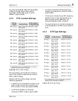
The SIMPRO-100 Relay processes ac and dc
inputs four times per power system cycle. During
every processing interval, it updates the state of
each protection element and logic function. The
details of this activity are described in Appendix
B: Control Equations & Relay Logic. The
Sequential Events Recorder (SER) function
operates by monitoring a user-defined subset of
the protection element results, contact input
states, and contact output states. When any of
the monitored elements changes state, the relay
adds a record to the SER memory. Each record
includes the date and time of the state change,
the name or alias of the monitored element, and
the element’s final state. The relay stores the 512
latest records sequentially in nonvolatile memory.
You can view the stored information using a PC
connected to the front- or rear-panel serial ports.
This instruction manual subsection outlines the
SER function settings. The SER settings include
settings which trigger entries into the event record
and alias settings that allow you to customize the
way the recorded data is displayed. Chapter 9,
page 117 describes the format and contents of
the SER reports.
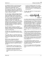
Setting Prompt
Setting Range
Setting Name =
Factory Default
Protocol
ASCII, MOD
PROTO = MOD
Baud Rate
300 – 19200
SPEED = 2400
Parity
O, E, N
PARITY = N
Modbus Slave ID
1 – 247
SLAVEID = 1
Summary of Contents for SIMPRO-100
Page 1: ...SIMPRO 100 Motor Protection Relay Instruction Manual Document No PRIM 2400C ...
Page 12: ...Contents SIMPRO 100 x PRIM 2400C ...
Page 16: ...Contents SIMPRO 100 xiv PRIM 2400C ...
Page 42: ...3 SIMPRO PC Software SIMPRO 100 40 PRIM 2400C ...
Page 100: ...6 ASCII Serial Port Operation SIMPRO 100 98 PRIM 2400C ...
Page 127: ...SIMPRO 100 Event Analysis 9 PRIM 2400C 125 Figure 9 2 Example SER Report ...
Page 136: ...10 Maintenance Troubleshooting SIMPRO 100 134 PRIM 2400C ...
Page 138: ...A Firmware Versions SIMPRO 100 136 PRIM 2400C ...
Page 206: ...D SIMPRO PC Compatibility Features SIMPRO 100 204 PRIM 2400C ...
Page 214: ...E Motor Thermal Element SIMPRO 100 212 PRIM 2400C ...
Page 230: ...F SIMPRO 100 Relay Settings Sheets SIMPRO 100 228 PRIM 2400C ...
Page 239: ......

