Additional information on the SIMOGEAR geared motor
11.2 Specific data motor
SINAMICS G115D distributed drive
428
Operating Instructions, 12/2020, FW V4.7 SP13, A5E48681219B-002
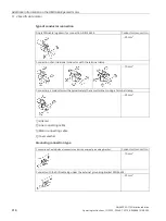
Procedure
1.
Remove the fan cover.
2.
Loosen the fastening screws of the brake.
3.
Screw the sleeve screws further into the solenoid using an open-ended spanner.
4.
Tighten the fastening screws of the brake.
5.
Check the air gap s
LN
in the vicinity of the screws using a feeler gauge.
6.
If necessary, correct the air gap s
LN
and then check it again.
7.
When combined with manual brake release:
Check the setting dimension s
HL
and correct s
HL
if necessary.
8.
Mount the fan cover.
You have now set the air gap.
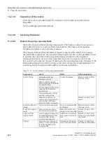
Table 11- 23 Air gap values
Brake type
Nominal air
gap
s
LN
(+0.1 / -0.05)
Maximum air gap for
Reference
gage
s
HL
Standard excita-
tion
s
Lmax.
Overexcitation
s
Lmax.
mm
mm
mm
mm
L4
0.2
0.5
0.7
1.0
L8/5
0.55
L8
0.5
L16/10, L16/13, L16
0.6
0.8
L16/20
0.5
L32/23
0.3
0.85
0.9
1.5
L32
0.75
L32/40
0.65
L80/50, L80/63
0.9
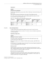
Table 11- 24 Tightening torque for the brake screw
Brake type
Thread size
Tightening torque
Siemens
Brake supplier
Nm
L4
INTORQ BA BFK458 (06E)
3 x M4
2.8
L8
INTORQ BA BFK458 (08E)
3 x M5
5.5
L16
INTORQ BA BFK458 (10E)
3 x M6
9.5
L32
INTORQ BA BFK458 (12E)
3 x M6
9.5
L80
INTORQ BA BFK458 (14E),
INTORQ BA BFK458 (16E)
3 x M8
23
11.2.20.4
Replacing the friction lining
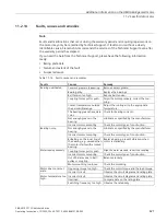
WARNING
Unintentional starting of the drive unit
Switch off the power supply to the drive unit.
The brake must be in a torque-free condition.
Secure the drive unit to prevent it from being started up unintentionally.
Attach a warning notice to the start switch.


